Category Archives: Hacks

opencodi – building a new firmware for Pillar Codi robot

All project files are now on github:
Now here’s the skinny:
My nephew got a Codi robot a few years back. The toy is pretty lame and definitely not worth the > $100 that my sister paid for it. We played with it for about 10 minutes and it never got used again. Today I pulled it off the shelf to start reverse engineering it in hopes that I could make it into something fun and useful. 
Currently the robot only has the most basic functions as I can’t even get my Codi Parent app set up (The software interface from Pillar used to configure the device) as I can’t get past email verification. I have yet to get anything but an automated email response from Pillar Customer Service so I can’t even get the unit working as originally intended. It is essentially a paperweight at this point.
Coming up with a new firmware for this device is worth the time for a few reasons:
  1. These devices are cheap and readily available on ebay
  2. They look like a Reddit avatar
  3. They have all the right peripherals to make a cool IoT device
  4. The company is unresponsive and maybe out of business
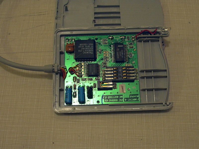
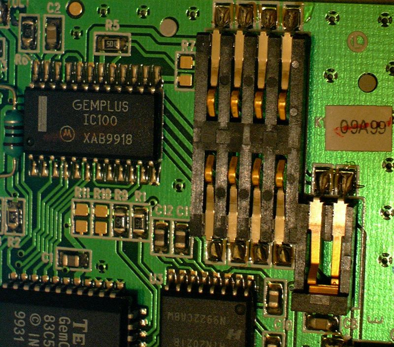
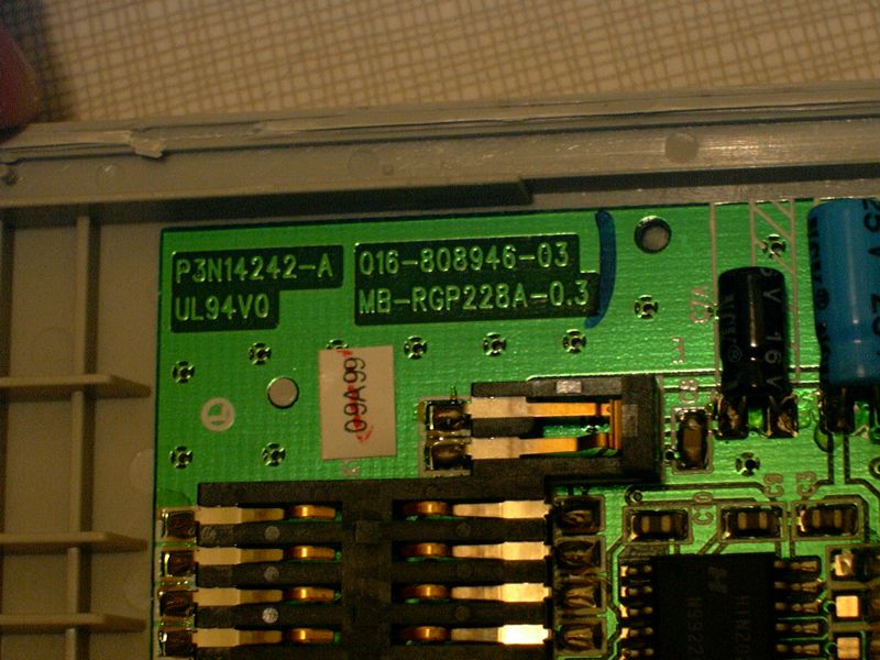
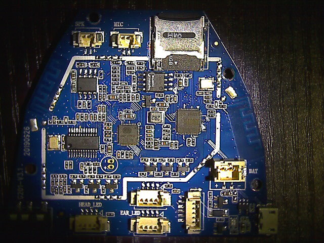
I have disassembled the toy and found what hardware it is using:
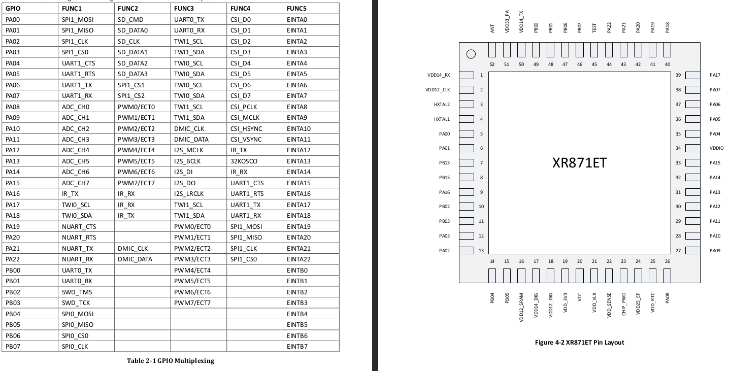
  • Main processor: XR871ET – Datasheets | SDK
  • Audio processor: A101
  • Bluetooth(?): JL AS20AP24150
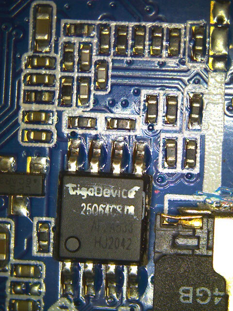
  • Storage: GD25Q64C – Datasheet
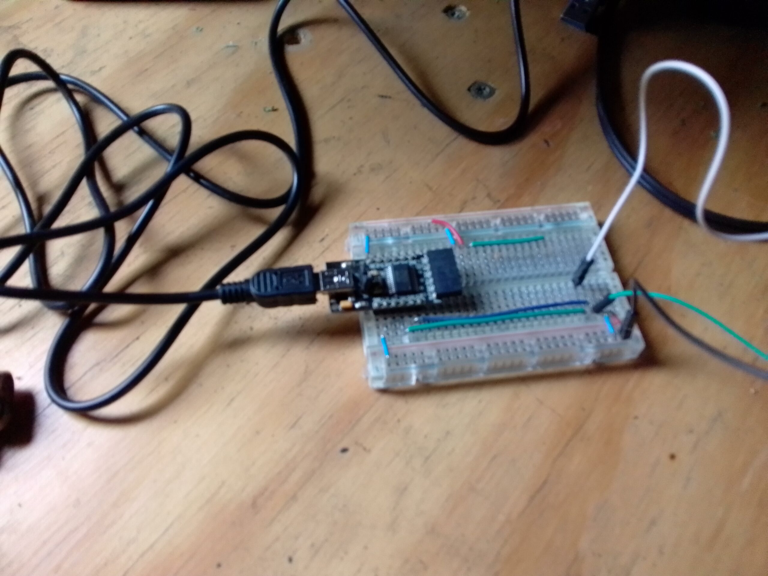
If I plug the robot into my Linux machine and run dmesg I get this error:
usb 3-3: new full-speed USB device number 60 using xhci_hcd
usb 3-3: Device not responding to setup address.
usb 3-3: device not accepting address 60, error -71
usb usb3-port3: unable to enumerate USB device
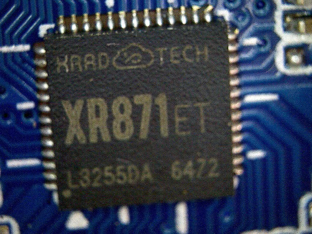
The chip does not have a USB connection, only UART and there is no built in USB to Serial converter on the board. Some tracing has confirmed that the USB port does connect to the UART of the chip using a non standard USB wiring configuration.
  • USB Pin #3 connects to Pin #49 UART0_TX
  • USB Pin #4 connects to Pin #48 UART0_RX
I have a USB to serial converter on the way (the one I have doesn’t seem to be working) and found a male micro USB plug with all 5 pins available to make the connection interface.
The USB pads on the back of the board connect to the JL AS20AP24150 chip.
  • DM pad connects to Pin #3
  • DP pad connects to Pin #4
Connecting a USB cable to these pads according to the label produces the same error in the terminal as seen above. I need to find a datasheet on this chip to see if I will need to reprogram it and why there are these breakout pads.
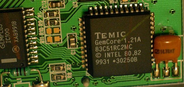
I am having trouble definitively identifying this chip and finding a datasheet and could use some help on this. Here is the chip:
 

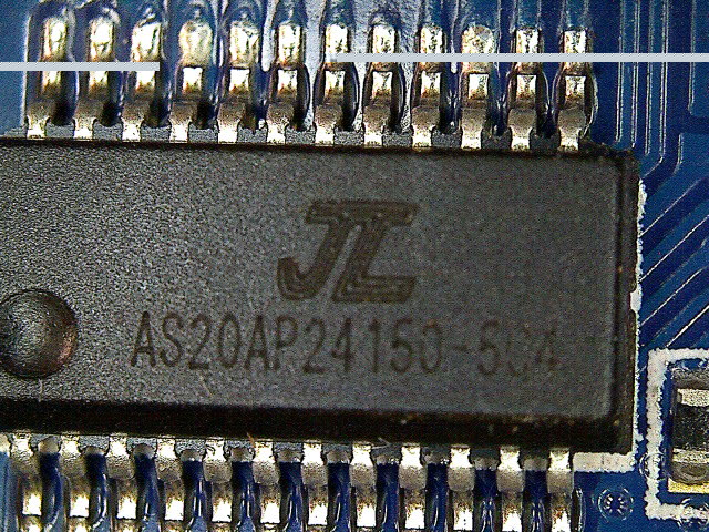
Can someone find this please!!!???
Finally storage is handled by a GigaDevice 25Q64CS chip and a 4Gig SD card.
Road-map:
  1. Acquire USB to Serial converter and create custom USB plug for reading/writing firmware to XR871 chip.
  2. Determine if existing firmware image can be de-compiled and edited or if a new FW will need to be written from scratch.
  3. Trace out all connections and create a detailed schematic of the motherboard.
  4. Create custom firmware. Can I make this thing run Linux?
  5. Use Codi as a control hub for smart devices similar to Siri or Alexa… Mycroft or Rhasspy?
I am open to any ideas, suggestions or collaborations.

Installing Zenmap in Ubuntu 22.04

There are a few tutorials out there claiming to instruct one on installing Zenmap in newer versions of Ubuntu, unfortunately all the ones I have found simply do not work. The big problem is that Python 2  and pyGtk have been completely phased out and are no longer available in Ubuntu. Attempting to install any currently available .deb packages will result in failure.

FEAR NOT!!!! The nmap team has updated their code to Python 3 and the entire nmap suite can be installed quite easily from source. Zenmap, with a minor tweak to the config file will  work on Ubuntu 22.04 (LTS)!

OK, let’s get into it!

This install will be performed from the command line so get started by opening a terminal…

1: Install prerequisites

$ sudo apt install build-essential checkinstall zlib1g-dev libssl-dev libcurl4-openssl-dev

2: Get the source code from github

$ cd ~/Downloads
$ wget https://github.com/nmap/nmap/archive/refs/heads/master.zip -O nmap.zip
$ unzip nmap.zip

$ cd nmap

3: Fix Zenmap config file

There is an error in the current Zenmap config file and if not fixed Zenmap will not be able to find your nmap binary.

$ nano zenmap/share/zenmap/config/zenmap.conf

Navigate to line 60 and fix the [paths] section. Change this:

[paths]
nmap_command_path = ../nmap
ndiff_command_path = ../ndiff/ndiff

To this:

[paths]
nmap_command_path = nmap
ndiff_command_path = ndiff

If you have already gotten everything installed but Zenmap can’t find nmap, you can do the same fix on the file in your home folder:

~/.zenmap/zenmap.conf

4: Compile and install

$ ./configure
$ make
$ sudo make install

5: Run Zenmap

For full functionality of Zenmap, it is recommended to be run as root.

$ sudo zenmap

Happy Hacking!

MyDIYCNC Desktop CNC Machine $20 GRBL Resurrection

About 8 years before the writing of this article i purchased a CNC machine from Amazon created by a company called MyDIYCNC. I was interested in the technology and the price was right at only $250.

It was easy enough to assemble and get working with Linux using their FabCAM software. Well, so it seemed at first…

When the z-carriage would retract, it would skip some steps once in a while and eventually drive the tool head into whatever I was trying to mill. While the company’s customer support was responsive I could never figure the issue out and the project got shelved.

Long story short the company is no longer around but the machine was. Sitting on my shelf, sadly doing nothing.

Then one day while shopping for 3D Printer upgrades, I ran across this Arduino kit on amazon that will replace the proprietary brains, motor controllers, and software with a well supported open source system, GRBL.

I put the Arduino and drivers into this 3D Printed enclosure:

I used the power supply that came with the MyDiyCNC kit as well as the original spindle relay. The two wires on the right go to the spindle pins on the Stepper Hat:

I soldered some female plugs from jumper wires onto my motor wires and attached them to the motor driver output. Color order from top (reset button side of board, see photo) is Blue, Red, Black, Green:

I hooked the 12V+/- output from the power supply to (yellow+, black-) to the controller hat. This is also where I pulled 12V for the 40mm enclosure fan.

Don’t forget to put a jumper on the enable pins (right of reset button).

Once everything was all hooked up I adjusted the motor controllers amperage to 400mA (for the stock motors that came with the kit, your mileage may vary) using this guide.

Now you just need to flash GRBL to your Arduino and get some software for your computer. Here are some helpful links and files that go me through the rest of the setup phase including jumper settings for microstepping:

The last tweaks to get it to work correctly was to set the X, Y, Z max speed to 350mm/min (Firmware Settings) and 1/4 micro-stepping (Jumper under motor driver).

Now you can calculate your steps per millimeter here.

Finally, the software to control it.

I have been using OpenBuilds Control and their integrated CAM software. It works fairly well, though the GUI is prone to crashing. Upside is that when the GUI does crash, the job still completes. Unfortunately he crashed GUI can make it difficult to find perfect zero again.

Universal Gcode Sender will definitely play with GRBL and control the machine. However I have yet to use it to actually run a job. I will post updates after I give it a try.

Feel free to post any questions in the comments section below!

Kenwood TS-440S IC-10 Upgrade and DIY CAT Control for Linux

My radio club, SFARC, has helped me get into an HF rig, namely the Kenwood TS-440S. This radio is a bit old (1986ish) but, IMHO, this thing is awesome. It has a fairly compact form factor, runs of my 12V off grid power without issue, and with the following upgrades will talk to my computer.

I first purchased a digimode cable that has opto-isolated audio input/output as well as a USB PTT coupler which is allowing me to experiment with digital modes on this transceiver. While this is great, I would like to be able to view and control the frequency of my radio from FLDIGI via HamCAT or hamlib. Turns out this will require a little bit of hacking (awesome!) to get it working.

Kenwood TS-440 Digital Interface Cable

Issue #1: The 13 pin DIN, ACC 2, only provides audio and PTT functions. If I want to provide a serial interface I need to use the 6pin DIN, ACC 1, interface. I need to build an interface cable.

Issue #2: This interface is a serial connection using TTL voltage (5.5v) but with the same logic as a standard serial port. I need an FTDI breakout board with inverted logic.

Issue #3: The 440 requires an upgrade kit (IC-10) to provide serial communication capabilities. This kit is semi-rare and costs about 50 bucks.

In this article issue #1 will be addressed with a six pin din plug ordered from amazon.

Issue #2 will be handled by an FTDI USB board I already have on hand and an XP virtual machine running FD_PROG to invert the logic. Unfortunately this makes this solution NOT 100% Linux. To resolve this I will use the command line Linux program ftdi_eeprom to clone my firmware and post it here so Linux only users can use ftdi_eeprom or flashrom to program their FTDI boards with ease.

Issue #3 is easily resolved by ordering the chips individually or by purchasing one of my $15 IC-10 kits from eBay.

IC-10 Chipset for Kenwood TS-440 / R5000

#1: Build the plug.

After receiving the plug from Amazon, I repurposed a shielded USB cable to build the plug. I hooked up all the wires even though CTS/RTS were not required. RFU style as it were. Perhaps adding flow control in the future would speed things up. I don’t know I haven’t tried. Anyway….

Disassembled Plug

These are the pin numbers as viewed from the solder side:

  1. GND
  2. TXD
  3. RXD
  4. CTS
  5. RTS

Here is how I hooked up the 5 wire USB cable:

  1. GND -> Cable shield
  2. TXD -> Green
  3. RXD -> White
  4. CTS -> Black
  5. RTS -> Red
Wiring Diagram

#2: Install the chips.

After I received my chips, I installed them following this guide. To sum up, remove the top and bottom cover from the radio. Then remove the face-plate screws and then loosen the 5 small screws for the metal grounding plate so it may be removed. Once this is done the chip slots will be exposed ( they are the only two empty slots on the back of the face-plate ). You will need to use a flat surface to bend the pins slightly inwards so that they will line up with the sockets when you insert them. Pay close attention and make sure the chips are fully seated properly into the sockets.

Once this is done reassemble the radio and ensure that it is working properly. Now the ACC 1 port has serial com capabilities.NICE!

#3: Hook Up the FTDI Breakout Board

The only pins required for communication are GND, TRX, and RTX. You supposedly can use a 5 wire connection using CTS/RTS flow control but it is not necessary. The FTDI breakout I used for this project only made CTS and DTS readily available so I went with the three wire setup. There may be advantages to having flow control and I would be interested to hear input on this in the comments.

My Notes

Attach the TX from your rig to the RX on the FTDI and the RX from the rig to the TX on the FTDI. GND goes to GND.

FTDI on the proto board

#4: Program the FTDI Board

Although the wiring is done, we still need to invert the logic on the FTDI board. There is no linux app to easily do this so I ran the FD_PROG utility using an XP virtualbox install to run this program. There are multiple drivers available from FTDIChip, make sure you use the correct driver for your system.

If you don’t have a windows install to program your FTDI chip, you can flash the following firmware to your FTDI chip using ftdi_eeprom. This firmware has the inverted logic necessary to communicate with your rig.

  1. FTDI Firmware File
  2. ftdi_eeprom Config File

Download both files to the same location, plug in the FTDI and program it. Something like this:

ftdi_eeprom --flash-eeprom ftdi.config

#5: Time to play radio!

You can now use FLDIGI or similar to read/send the frequency and PTT key your radio. Software config is beyond the scope of this article, but this is what it looks like:

If you enjoyed this article you can support me by subscribing to my YouTube channel and/or visiting some links from my sponsors. Thanks!

References:

  1. FTDI Chip Utilities
  2. FTDI Chip Drivers
  3. Installing an IC-10 kit into a Kenwood TS-440S/AT HF Radio
  4. TS 440 Serial Communications Interface
  5. TS-440 SAT Modifications
  6. Kenwood TS-440 mods reviews software and diagrams
  7. Build an Easy USB Computer Interface for Your Old Kenwood Rig

Charge Bauer 20v Lithium Packs Using a Balance Charger

This all started the other morning when I realized I had left my Bauer battery pack and charger outside in the rain. Long story short you can use the plug from a broken charger to make an adapter to charge your battery packs with a RC Vehicle Balance Charger.

Bauer 20v + TBS Charger
Bauer 20v Pack Connected to Balance Charger

The Story

After sitting, plugged in, in the rain, overnight, there was a large amount of blue material on the battery and charger connections.

Pushing the button on the battery showed full charge, so I cleaned off the connections and tried it in my drill. No dice. I dissembled the battery pack by removing the four torx screws on the bottom. There was corrosion on the inside of the connector but everything else looked OK. I cleaned off the connectors from the inside and reassembled the battery.  JOY! The battery is working again.

Things were not so good for the charger. Under the charging board there was a huge black spot where a bank of resistors had fried.

Magic Smoke Stain

I was thinking about repairing it when I noticed that the plug part inside the charger was a self contained unit. Not only that, the connection plug for the sense port was the same as the plugs on the batteries for LiPo  RC batteries (eg Drone Batteries).

The pin-out on the above mentioned plug is not the same as a standard RC LiPo battery, but all the necessary components (and then some) are. If you are looking at the balance plug (on a Drone Battery for example) with the bumps facing down, the leftmost wire is ground and the next wire to the right is the voltage of one cell. The third wire is the voltage of two cells, the fourth wire is the voltage of three cells and so on depending on how many cells you have.

The Hack

In a nutshell we need to make the Bauer battery pin-out match a stander RC Lipo Battery. The finished adapter will look something like this:

Bauer Adapter Dongle

You will need security torx bits (with holes in the middle) to remove the bottom plate from the charger. Then just unscrew all the Philips screws until you have just the battery plug unit. Unplug the 6 wire plug from the board and cut the red and black wires as close to the board as possible.

Using a small screwdriver to press down the tabs, remove the pins from the 6 pin plug (they need to be rearranged).  The small yellow and red wires (that you just pulled from the plug) are for the battery’s internal temperature sensor, we don’t need to monitor this sensor so we can use these wires to finish our plug. De-solder the small yellow wire and solder it with the main negative (big black wire). De-solder the small red wire and solder to the main positive (big red wire).

Move small red wire to big red wire post. Move yellow wire to big black wire post.

Solder a battery connector (salvaged from old battery pack) to the main positive and negative (big wires). Finally reinsert the pins into the plug as pictured:

Bumps Up: Red, Grey, Black, White, Blue, Yellow

The adapter is finished and just needs to be tested. Plug the adapter into your Bauer battery pack. Using a volt meter your battery plug should show about 20v. With the bumps facing down your 6 pin plug should test as follows (voltages are approximate and will vary depending on the level of charge):

  1. Yellow: (-V)
  2.  Blue: (+3.7)
  3. White: (+7.4)
  4. Black: (+11)
  5. Grey: (+14.7)
  6. Red: (+18.4)

Using the adapter you can now connect and charge your Bauer tool packs. In the program mode set your battery type to 3.7V (Lithium Poly or LiPo). Set the amperage to match the AH listed on the side of the battery pack. The charger will auto-detect the number of cells (5) and  after doing a quick balance on the cells will charge the pack until full.

LiPo Charge, Auto
Charging in full swing
Individual Cell Voltages and Balance Charging

In summary, this hack is very simple and could be considered an upgrade to the charger from HFT. Having the info display showing the voltage of each cell and balance charge mode are both great. There is also a fast charge that I haven’t tried, but this already charges my batteries quicker and more completely than the Bauer charger.

If you enjoy my articles, please consider visiting my sponsors links or subscribing to my YouTube channel. Thanks!!!

Amex / Gemplus Smartcard Reader – Usage and Hacking

View Post

Looking for Smartcard info downloads? You have been directed here and download links are below.

Many many years ago I had a post on my old website, artofconfusion.org, oulining the research I did to get the old free Amex smartcard readers to work on Linux. Analytics are showing that people are still looking for the post, so I have added the info and doc downloads here.

A few years back american express introduced the Amex blue, the first US credit card using smart card technology. During the release of this card Amex was giving away, free of charge, no questions asked, a card reader to be used with their cards. This page will provide an outline for hacking that gcr415 smart card reader you were lucky enough to acquire.

The gcr415 is no more than the gemplus serial smart card reader with some fancy Amex stickers on it. Any software or data-sheets related to the gemplus serial will work with the gcr415. 

My progress

Windows: found appropriate driver for my windows 2k unit installs and works to install the driver. Use the driver i have it in the archives for gempc410 serial card reader. Use the install exe then go to the add hardware wizard -> add other device and it should appear with 4 choices. The driver that works is gemplus pcr410p serial smart card reader. Once its installed it is listed in the hardware section under smart card readers. The utility recognizes the device and can tell when a card is being inserted and removed i don’t have blank smart cards yet so its difficult to play further.

Linux:

Got the goodies together to get the card reader working in Linux (slack 10 kernel 2.4). First you need PC/SC-lite installed then you install the driver. Once it installs you need to set up a proper /etc/reader.conf file. You can look at mine:

$ cat /etc/reader.conf

FRIENDLYNAME "GemPC410"
DEVICENAME /dev/ttyS0
LIBPATH /usr/pcsc/drivers/libGemPC410.so.0
CHANNELID 1

it works and if you run

pcscd –fg stdout

you can watch the daemon at work…

Then if you install the perl wrapper for pcsc you can use the tools like pcsc_scan in another terminal or after running the daemon in the backgroud. Cool thing about the perl wrapper is you can build runtime compiling apps to work with the reader.

Smartcard / Gemplus Related Docs

For more information and downloads, check out my old smartcard research page.

The Amex serial Smartcard Reader:

Let’s crack it open and see what’s inside:

Smartcard Dimensions:


Amazon Kindle Fire 5.3.1 Hacked – Rooted and new Rom

I just purchased a Amazon 5th gen kindle fire to use as a ground station for my drones. The device supports OTG and has the power needed to run the 3dr usb telemetry device.

Out of the box the fire is kind of useless for anything but an e-reader amazon buying tool.  Rooting and a ROM upgrade solves this! It is fairly simple, however the process is time consuming with lots of waiting (have something else to do like a book or a movie while you’re waiting on certain processes).

Step 1: Make sure you have 5.3.1.0 fire OS installed on device
Go to Settings -> Device Options -> Software Updates to check the version. My device shipped with 5.3.1.0 so I did not need to load a different firmware. Your mileage may vary.

If version is less than 5.3.1.0 follow This Guide instead.

If version is greater than 5.3.1.0 follow these instructions to install the 5.3.1 firmware. download from here

DO NOT attempt to downgrade a > 5.3.1.0 device below 5.3.1.0!!! This it will BRICK your fire.

Once version is 5.3.1.0 go to step 2

Step 2: Reset to factory settings
Go to Settings -> Factory Reset and perform a factory reset. This will reboot the device.

When device boots skip all set up and do not connect to WiFi yet (this will slow down any unwanted update process).

Step 3: Enable Developer Mode
Go to Settings -> Device Options and tap the build number seven times to enable dev mode.
Go to Settings -> Device Options -> Developer and turn on USB debugging and ADB.

Step 4: Download needed files
Download the latest SuperTool from RootJunky and extract somewhere you will remember.

Download the latest Nexus ROM for Fire Tablet but DO NOT extract it.

Step 5: Run SuperTool
From a command line navigate to the SuperTool folder and run the appropriate file. In Linux the command is
$ ./3-Amazon-Fire-5th-gen-linux-mac.sh
You will see a screen like this:

Press 2 and Enter to root device. First it will install KingRoot to your device which you will then have to run from your device when directed to do so. KingRoot will ask you to connect to WiFi.

You will likely have to run KingRoot repeatedly before it will work. Time to grab a book or a movie as this part takes time. Each time you run KingRoot it will reboot your device a few times and show progress on the screen. Each attempt takes about 10-15 minutes or more. After the first attempt I unplugged my device from the computer and had to run KingRoot a total of 4 times before it worked. Just keep trying.

Once root is gained plug your Fire back into the computer (you may need to cycle the ADB setting on your device for it to be recognized) and continue the SuperTool process following all instructions there. This will install SuperSu which will need interaction from you on the device. Follow the setup procedure according to the instructions in SuperTool.

Once this process is done run “Block OTA updates” to prevent accidentally losing root access.

Step 6: Install Rom via FlashFire
While still in SuperTool install FlashFire (option 6).

From your computer copy the zipped ROM file downloaded in Step 4 over to the INTERNAL storage of your Fire device.

On your device run FlashFire and follow these steps exactly, otherwise you risk the installation having problems:

Select the red plus (+) button to expand a selection of options, choosing Wipe.
Select System data, 3rd party apps, and Dalvik cache if they are not already checked.
Click the red plus (+) button again and choose Flash ZIP/OTA.
Search for the Nexus ROM that you’ve copied over and choose it.
Automount and Mount /system read/write need to be unchecked.
Drag Wipe to the top of the queue.

Hit the flash button to start the process.

This will take a few minutes and the screen might go blank for a while. It will eventually boot into the new ROM.

Step 7: Enjoy!
With new ROM installed be sure to update Google first. After it updates clear google app and framework cache and reboot.

Install apps. You will need EVERYTHING as this is a very vanilla ROM.

OTG works great with APM/Tower or DroidPlanner software.

Much faster, full play store support and NO ADS! Yay!