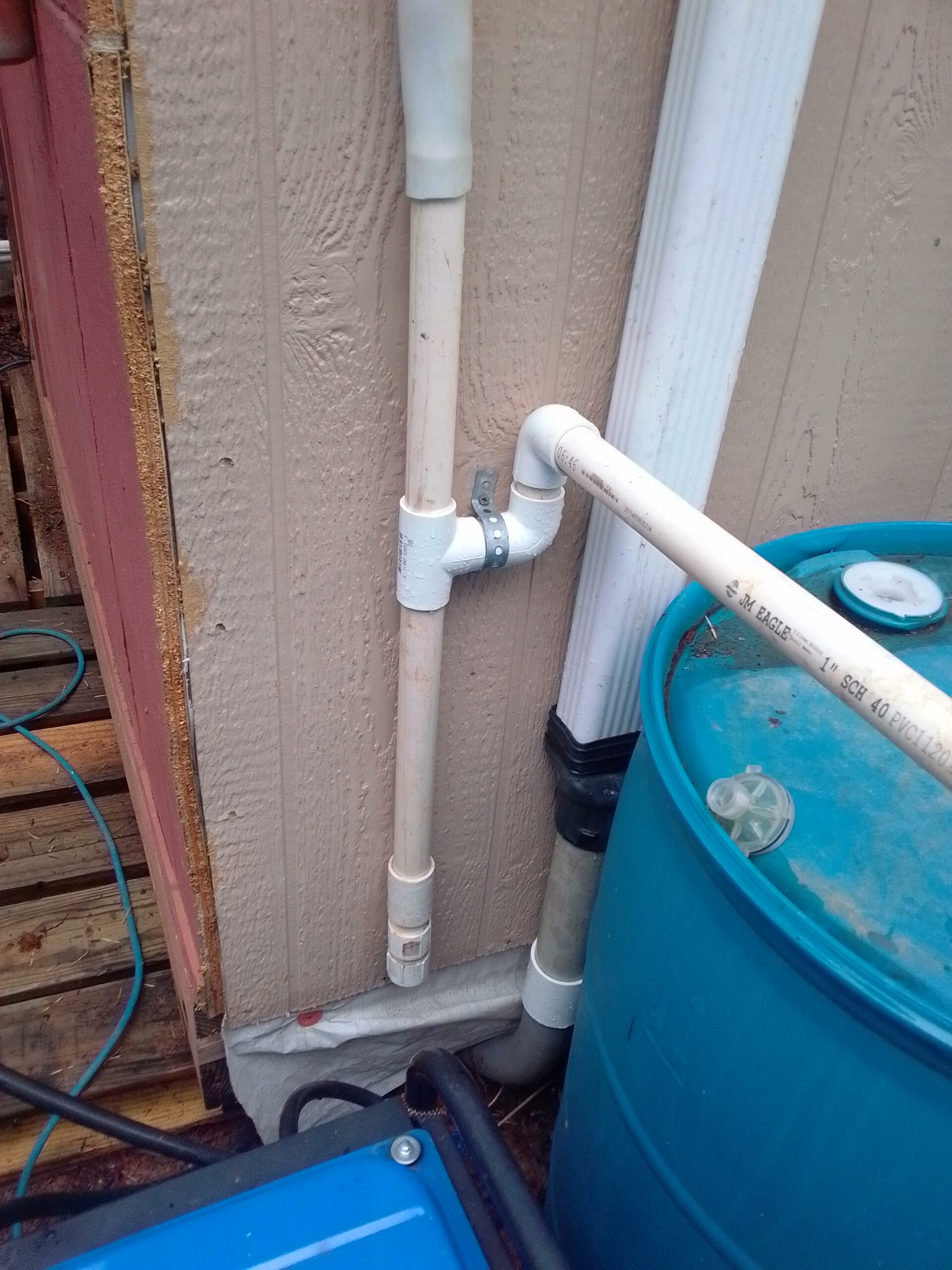
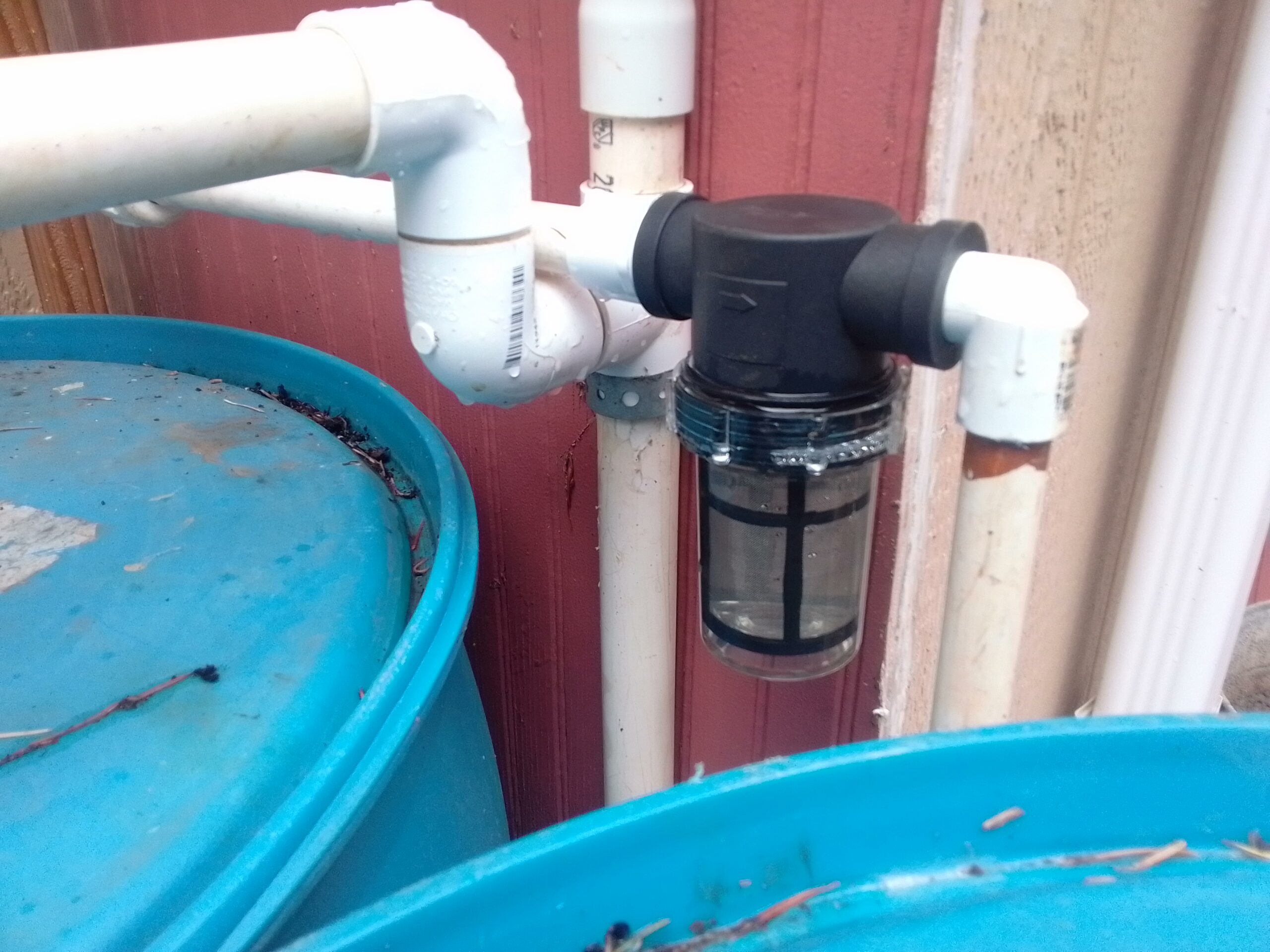
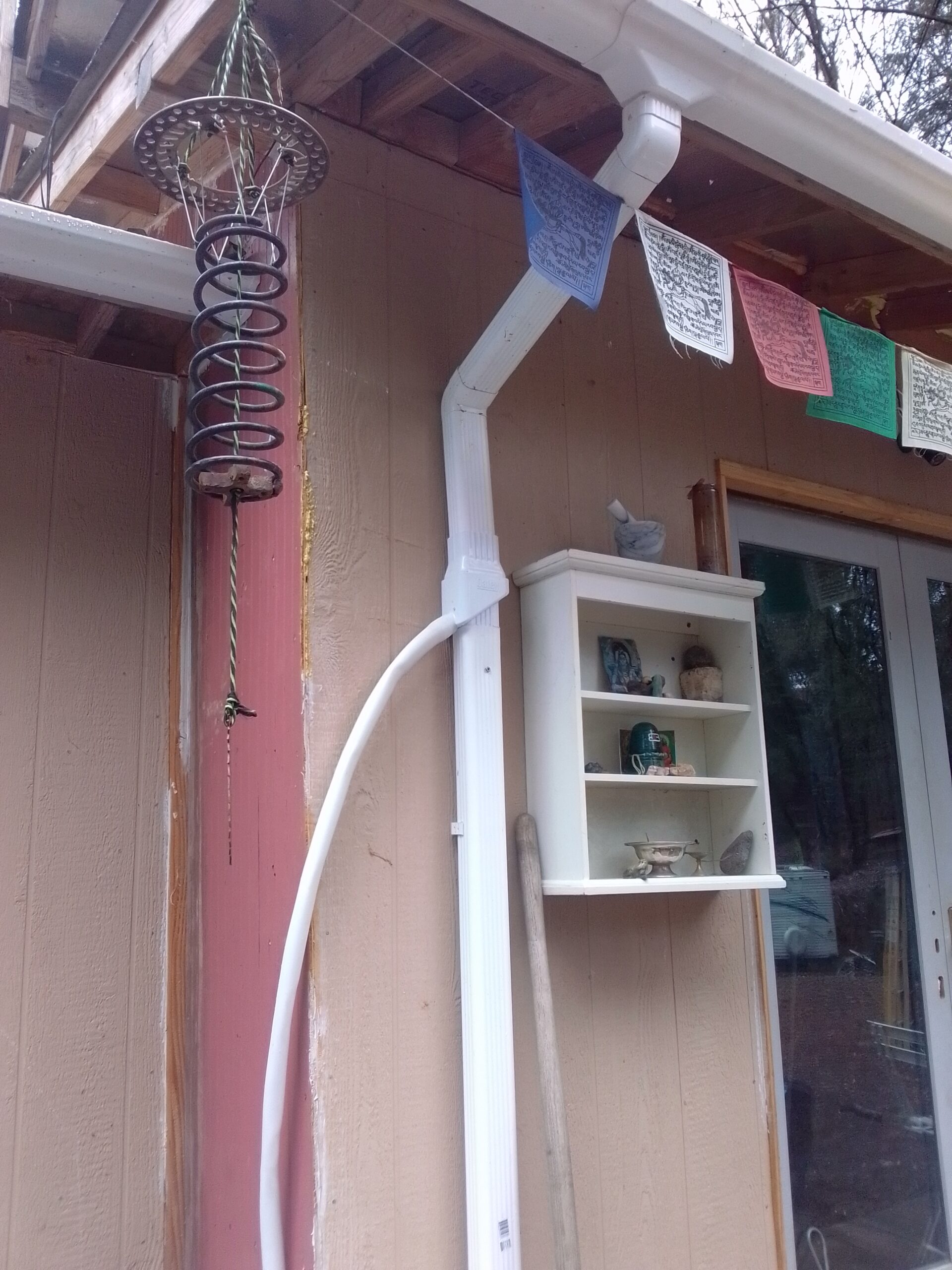
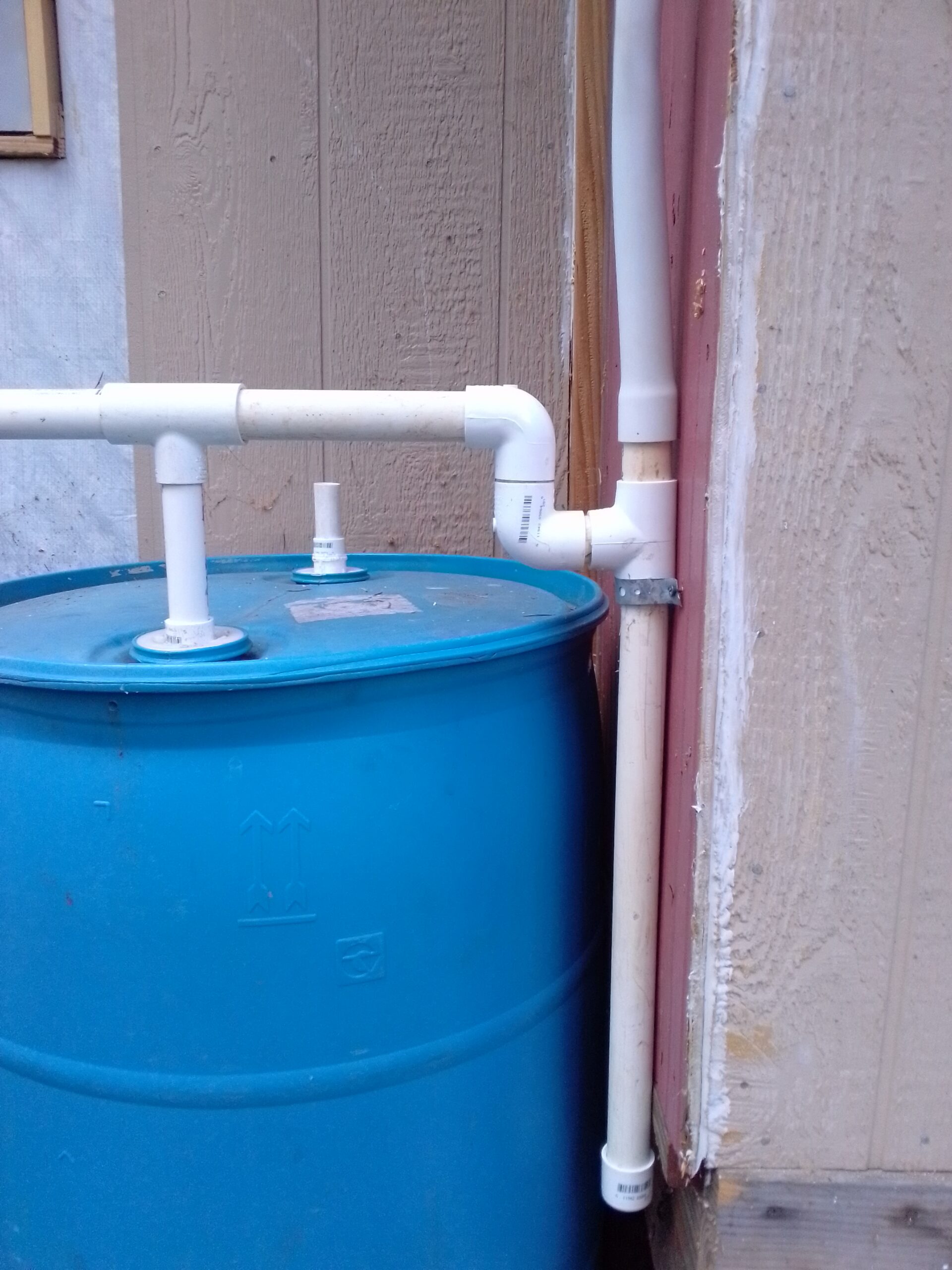
I have completed my rainwater collection system. All said and done I think I spent less than $100. The first time I did my dishes with rainwater was the first time I felt truely off grid. What an amazing feeling! Water from the sky!!!!
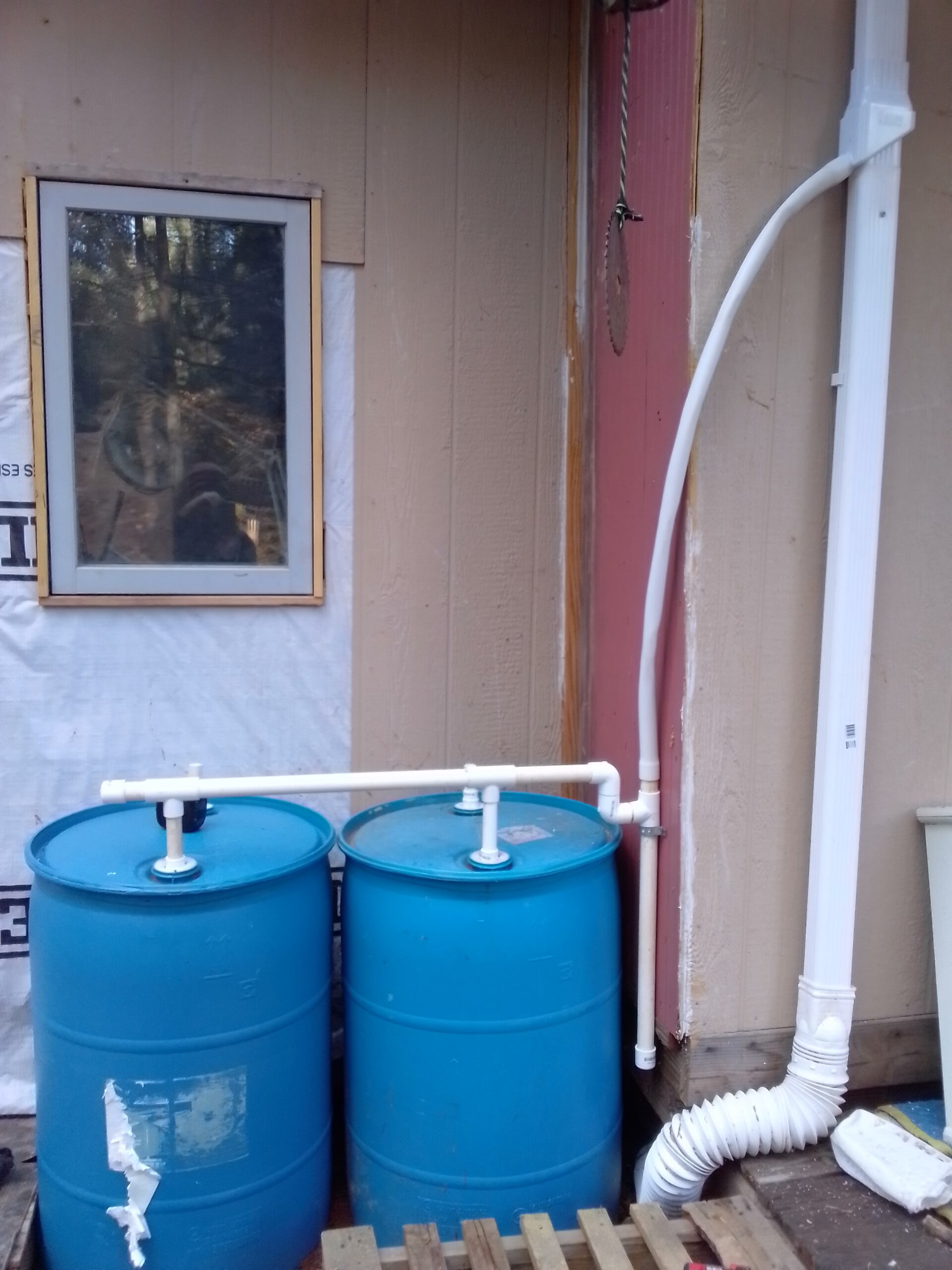
The barrells were salvaged from a construction company up the road. They originlly contained Blue Def for the company trucks. I figure this is OK as I won’t be drinking the water from this system and, of course, I rinsed the insides out as best as I could before putting them into use.
For the pump to pump the water into my house I used a water pump salvaged from an RV. If you can’t find one for free you can Buy one Here on Amazon for about $75.
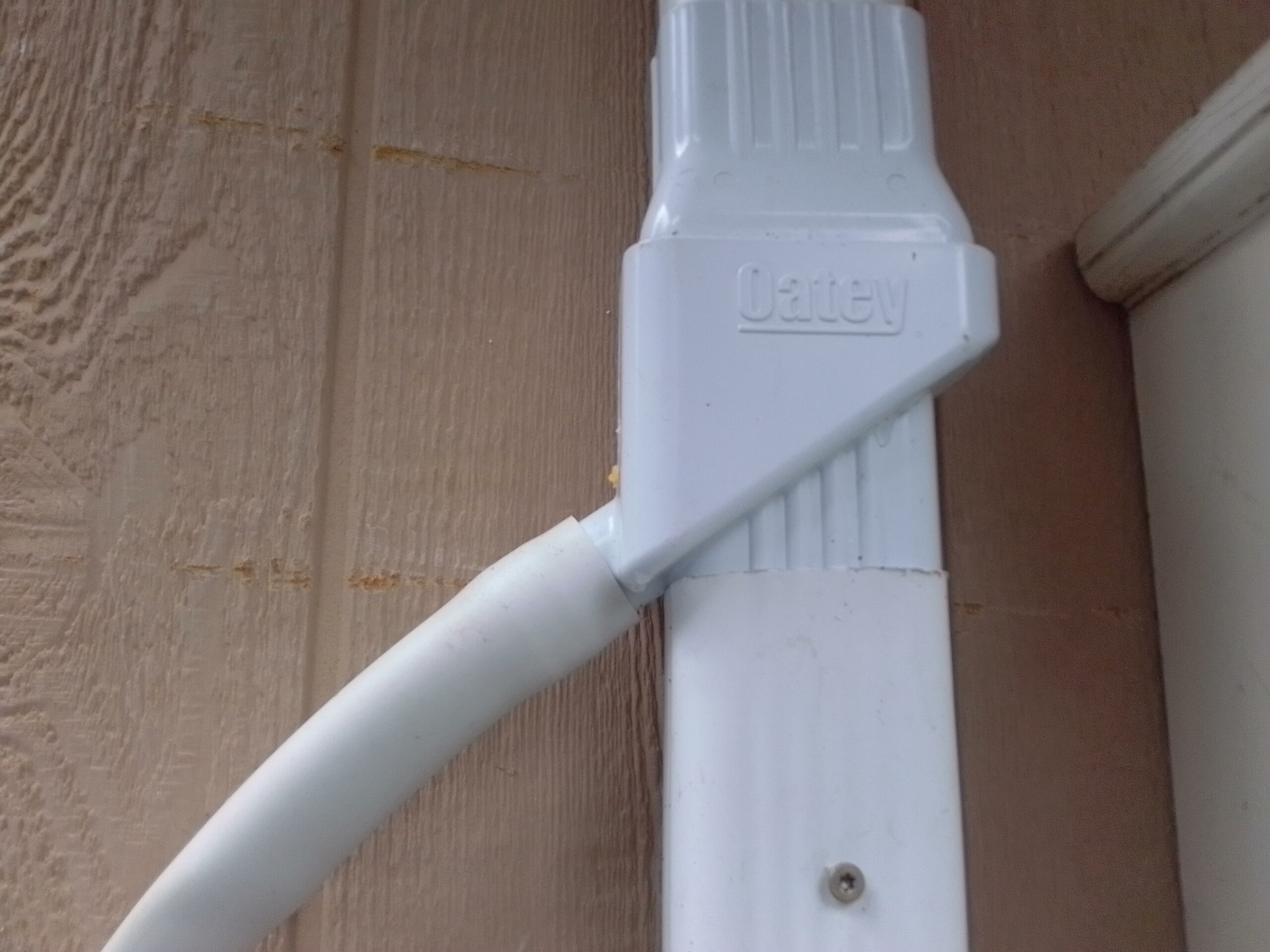
PVC P-Trap for particle / sediment collection. Cap on bottom unscrews for cleaning.Sediment Filter on Water OutputTanks installed!Oatey DownspoutBuy Oatey Rainwater Collector on AmazonP-TrapDay one of the build, only two barrels at this point.
My first spruce shipment came in last Friday! I decided to build some of the smaller parts first so I ordered the vertical stabilizer kit and the elevator kit. I already have the space to build these parts and I figured it would be an easy place to start. I was slightly mistaken about the easy. This “mistake” is actually working in my favor. It has given me time to perfect my mental build of the craft, see how the build process will be best accomplished, and is getting me mentally prepared for the meticulous nature of this undertaking.
Layout of elevator parts before milling.
The plans and instructions on building the empennage aren’t entirely clear and must be studied thoroughly. Much googling and reading of forums revealed that I was not the only one that found these pages of the plans “left to interpretation”.
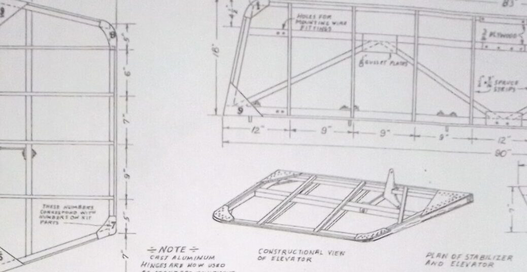
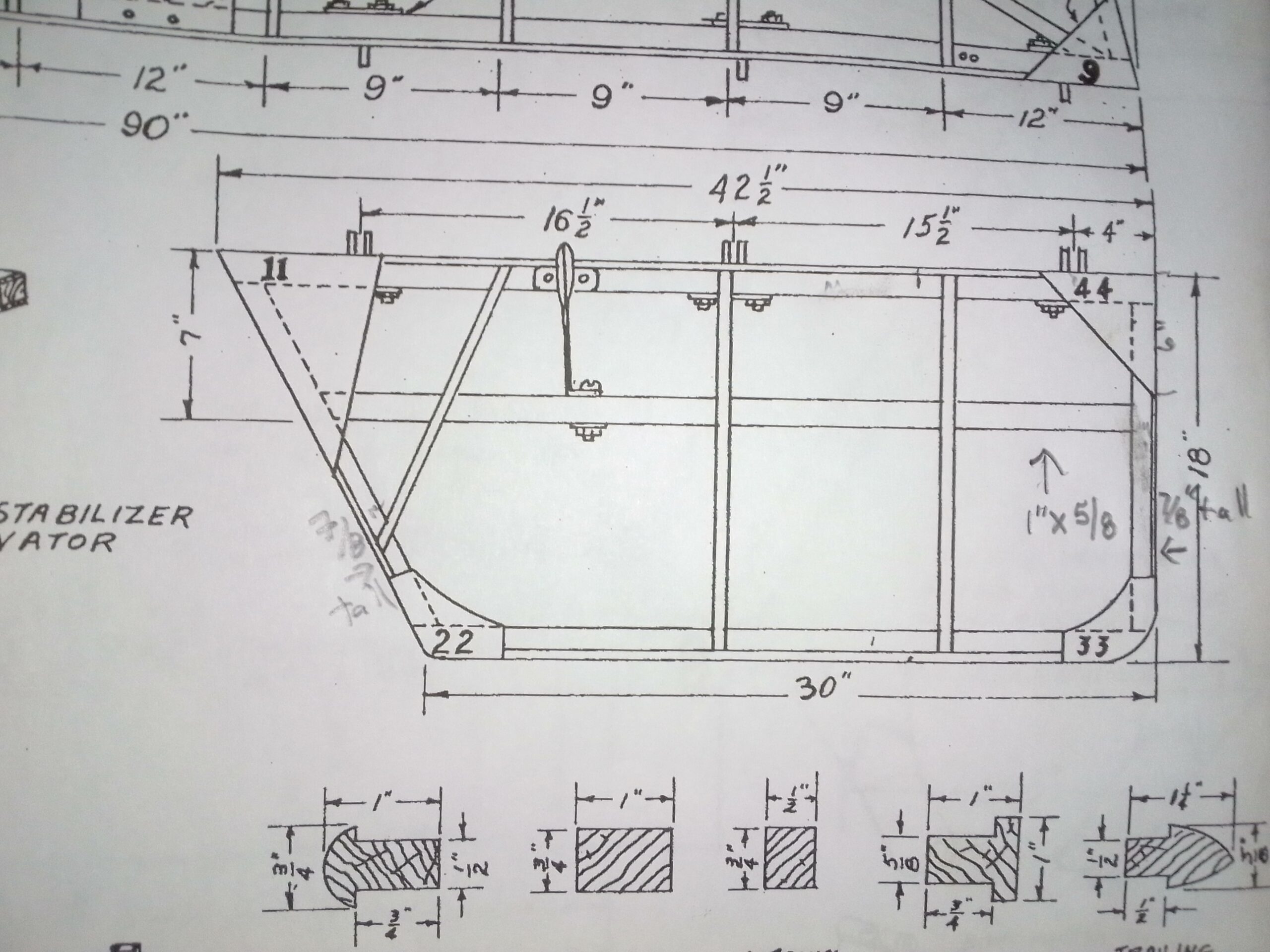
Elevator as pictured on the plans.
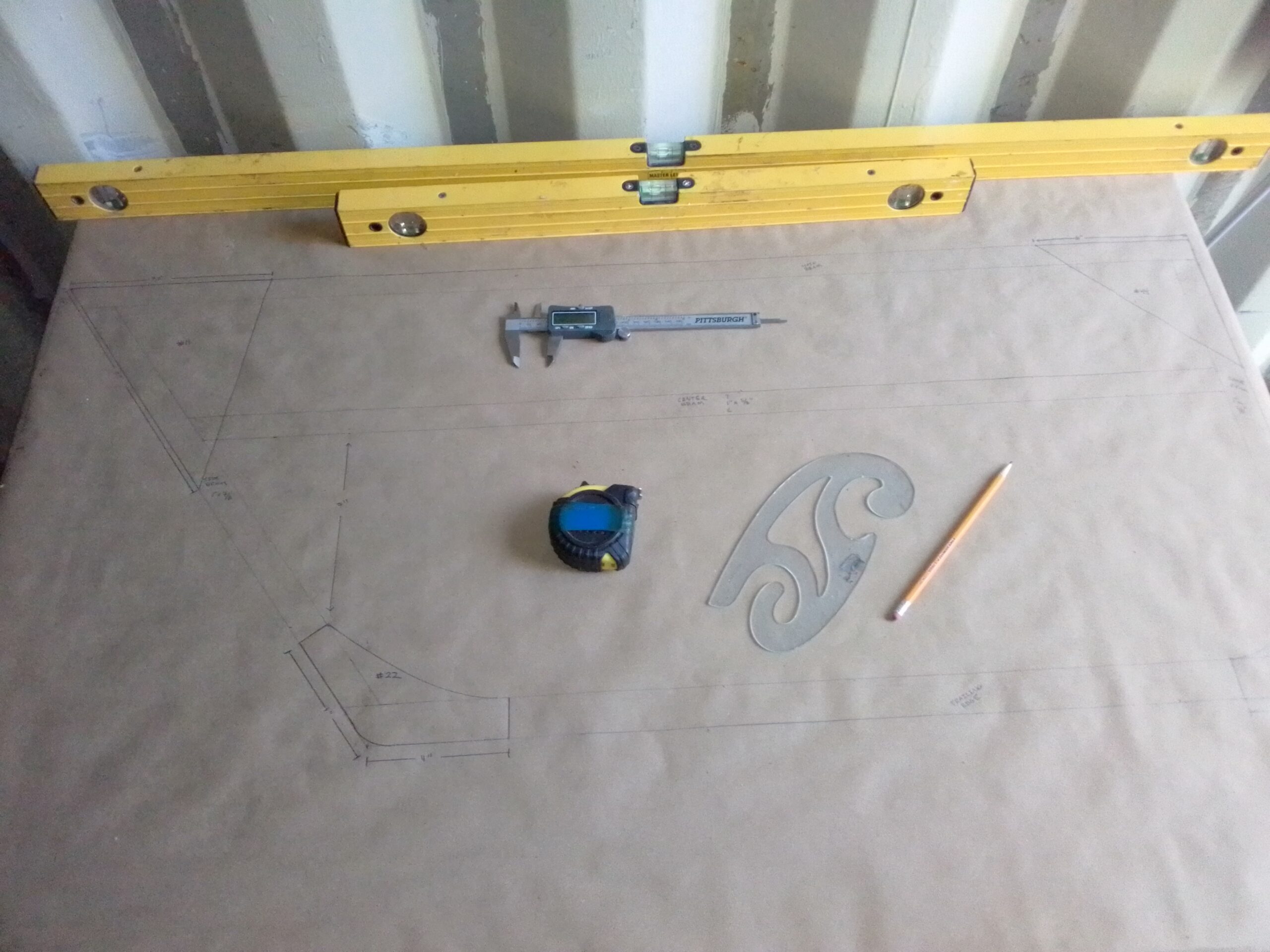
There are no definitive dimensions for the gussets. They are numbered with a note that says “These numbers correspond to parts in the kit.” The “kit” from aircraft spruce just contains a peice of 1/8 plywood for the gussets to be cut from. I could not find patterns or dimensions anywhere. Also the dimensions for the center beam seem to be only for the stabilizer and the correct dimensions for the center beam on the elevator must be deduced. The solution ended up being quite simple, I made a full scale drawing of the elevator. Once this was done, figuring out dimensions and designing the gussets was actually quite simple.
Caliper, straight edge, rulers and swoop stencil
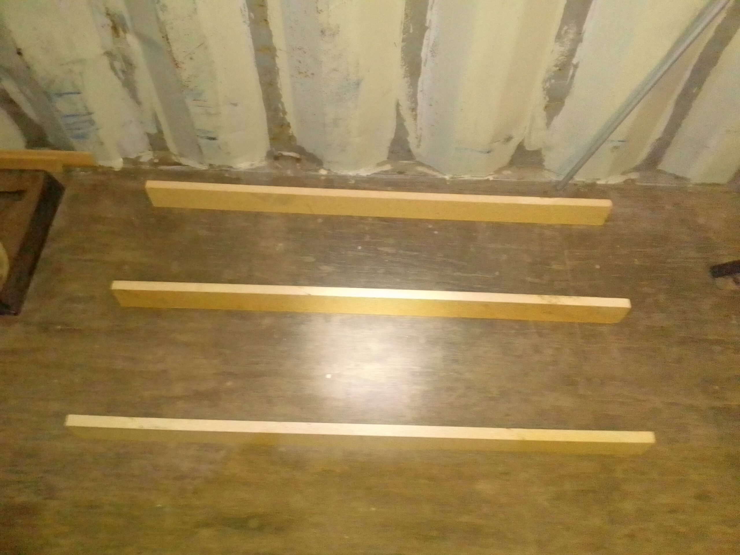
I began by constructing a simple build surface that I could screw wood to to form a jig for the elevator. I used some scrap particle board and made some 2.5″ spars with my table saw. I spaced these out on the floor, put a bunch of wood glue on the upward facing surface and then set my build surface (3/4″ particle board) on that. I weighed down the top with heavy things and let it dry overnight.
Spars for underside of build surfacesurface glued to spars weighted down overnight
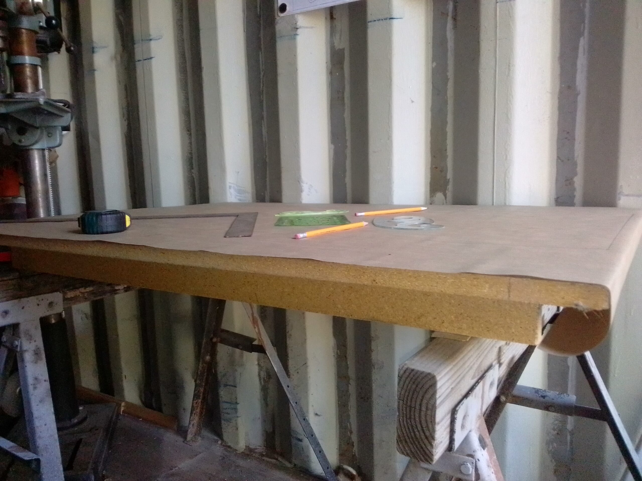
The next morning I screwed the “table” to my sawhorses with two 6″ screws. I put one screw down from the top and through the middle spar into each sawhorse. Then I used shims under the other spars to make the surface flat in all directions.
build surface attached to sawhorses and shimmed to perfect flatness
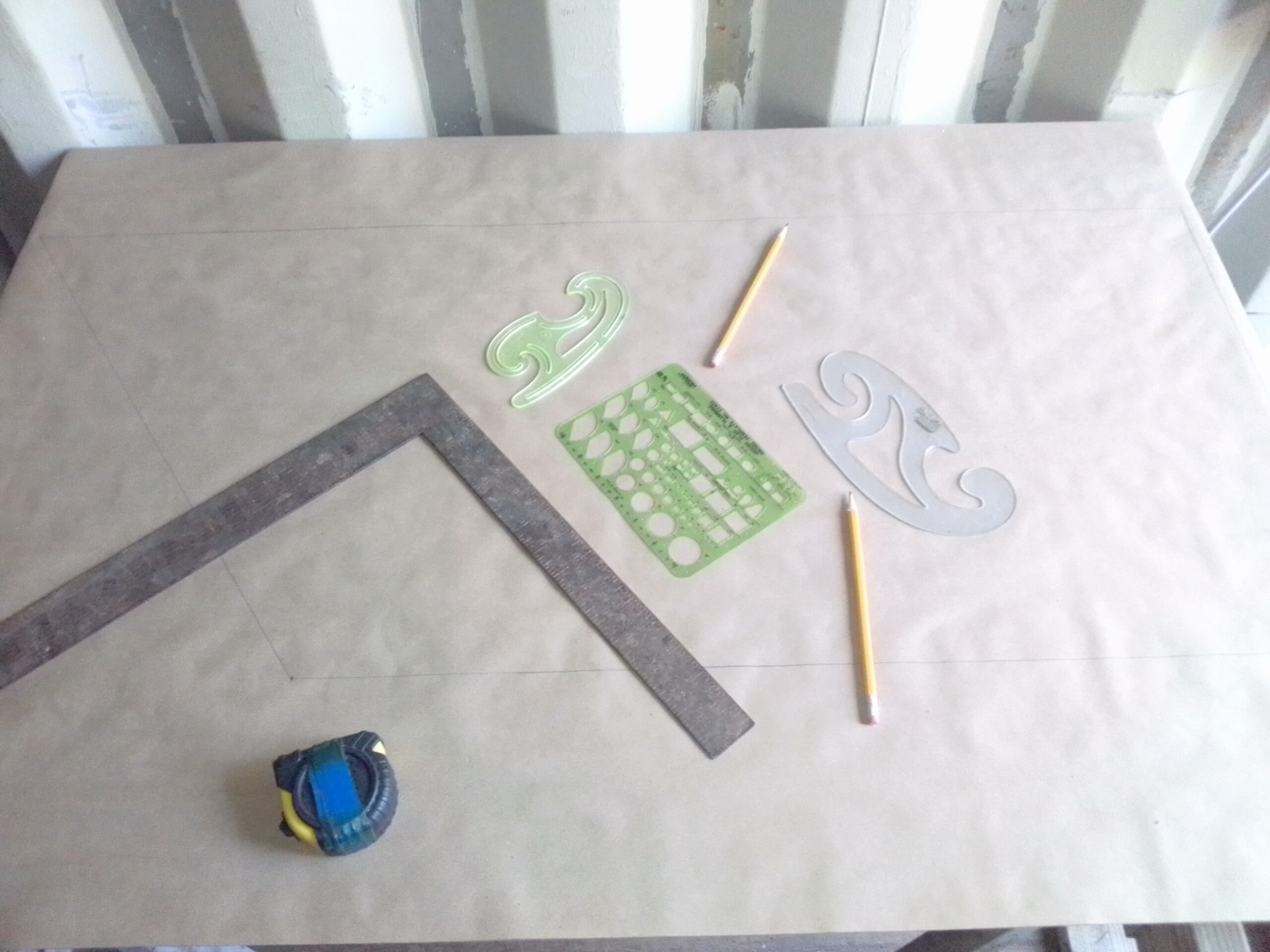
Once my surface was ready, I covered it with kraft paper and meticulously translated the elevator blueprint to full size on my build surface. I then came up with what seemed like the correct dimensions for the gussets and used the pictured swoop stencil thingy to do the rounded corners.
Stencils, rulers, a square, and some really sharp pencils.Translating blueprint to full size.
When it comes to holding gussets in place while glue dries, if you ask 5 builders you will get 10 suggestions on the best way to do this. The original plans call for cement covered flat head nails. It has been recommended by some to use a pneumatic nail gun to staple or nail them into place. Some say pull the fasteners, some say leave them in… Some say use weights, some say light clamps. Goodness… what to do? Well, after drawing up the full size plan, I’ve decided that building with a jig and just using small weights to hold the gussets while the epoxy dries is going to be the method for me. Both elevator pieces should be identical, so building everything in a jig makes the most sense. This also will allow me to miter and assemble the entire unit without having to glue anything until it is perfect.
I will be posting a YouTube video explaining this more thoroughly. I am also intending to come up with full size patterns for the gussets which I will make available on this website.
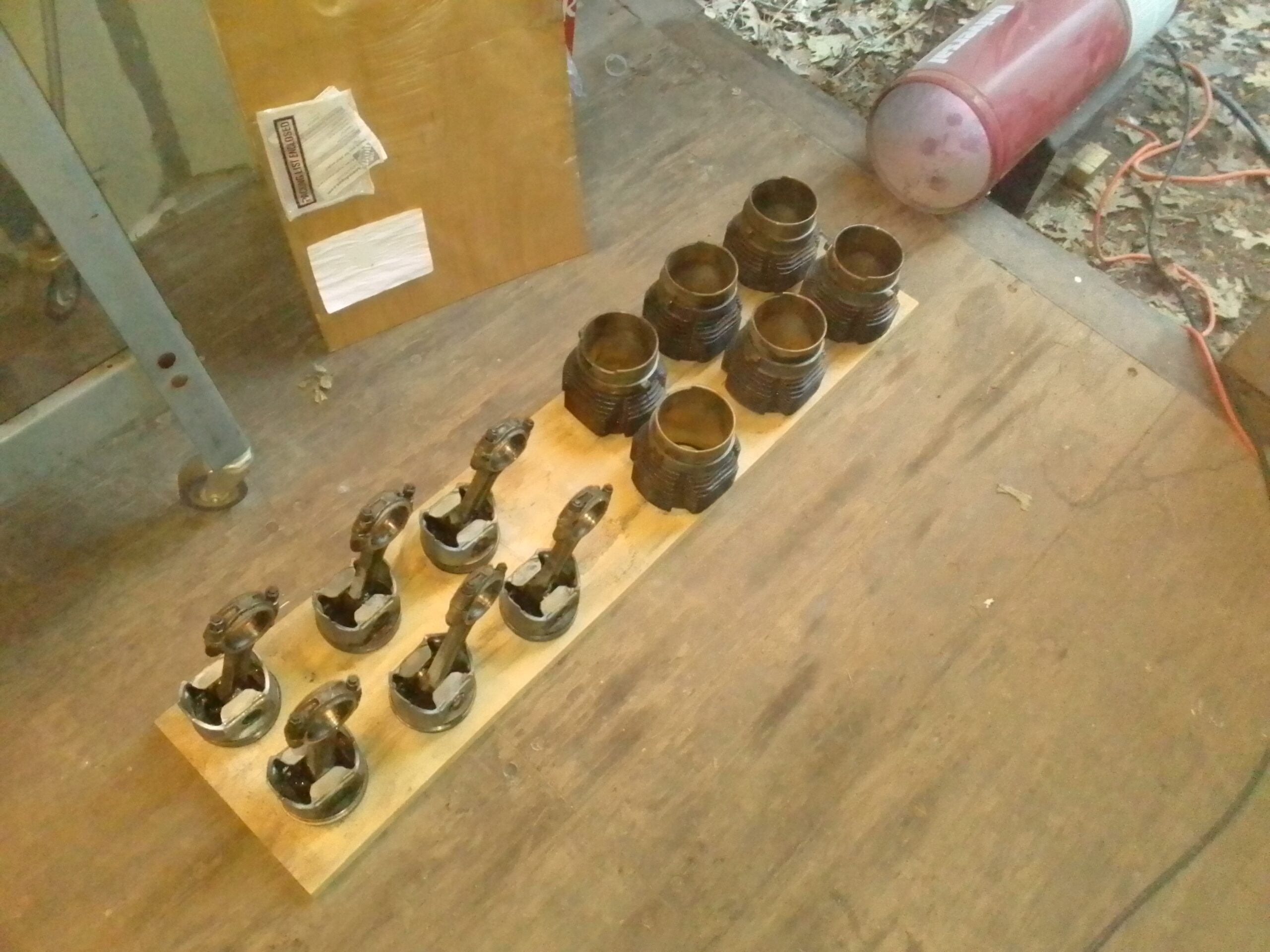
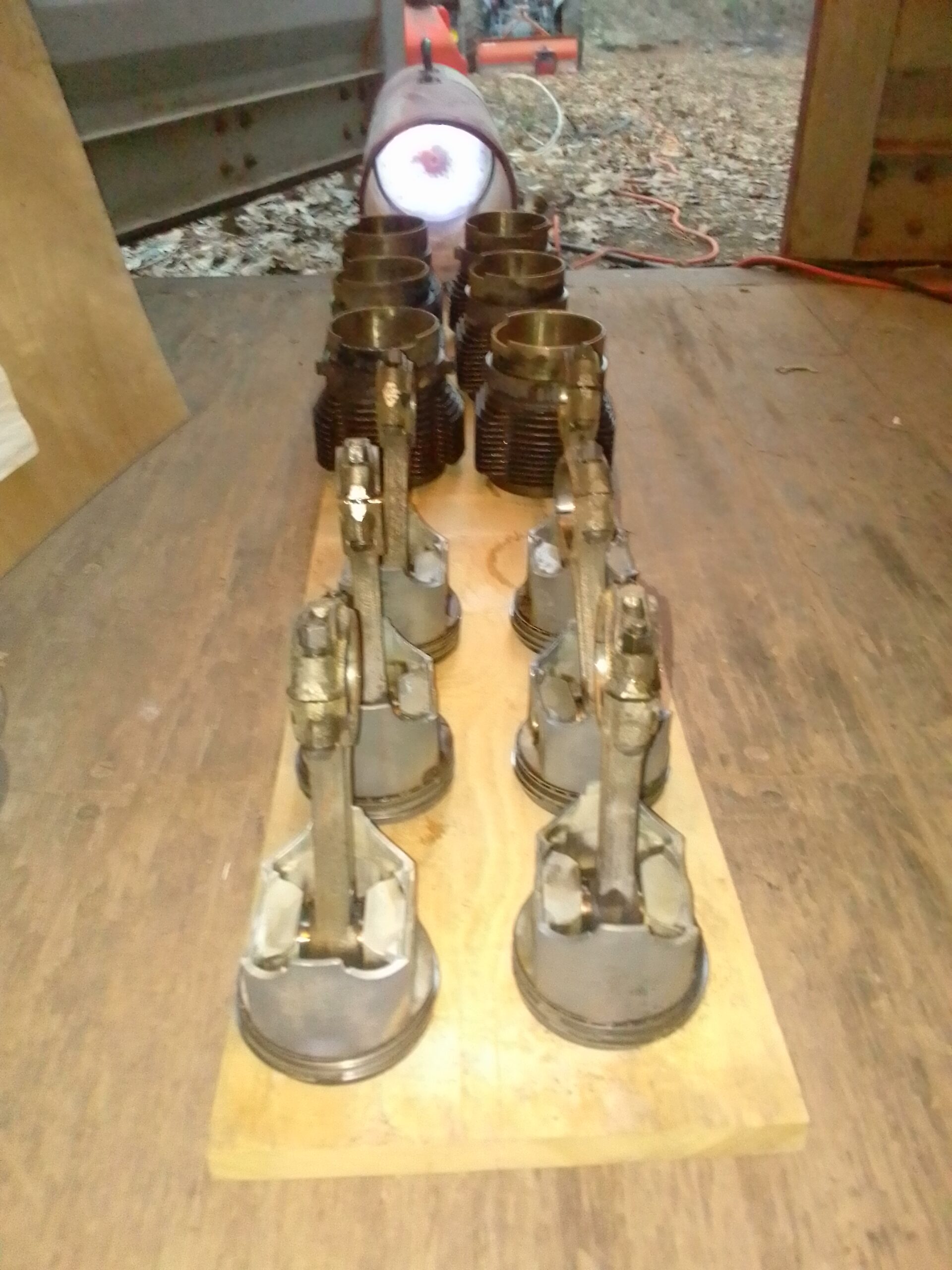
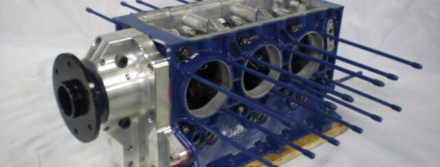
Using the same hot water and Purple Power process I soaked and pressure washed the cylinders, rods, and pistons in prep for core ship to Clark’s Corvair. Because these parts were made of steel and rust was an issue they required a bit more prep. After washing I immediately put them in front of the shop heater to dry:
Cooking of the water with shop heater150K BTU per Hour dried things quite well 🙂
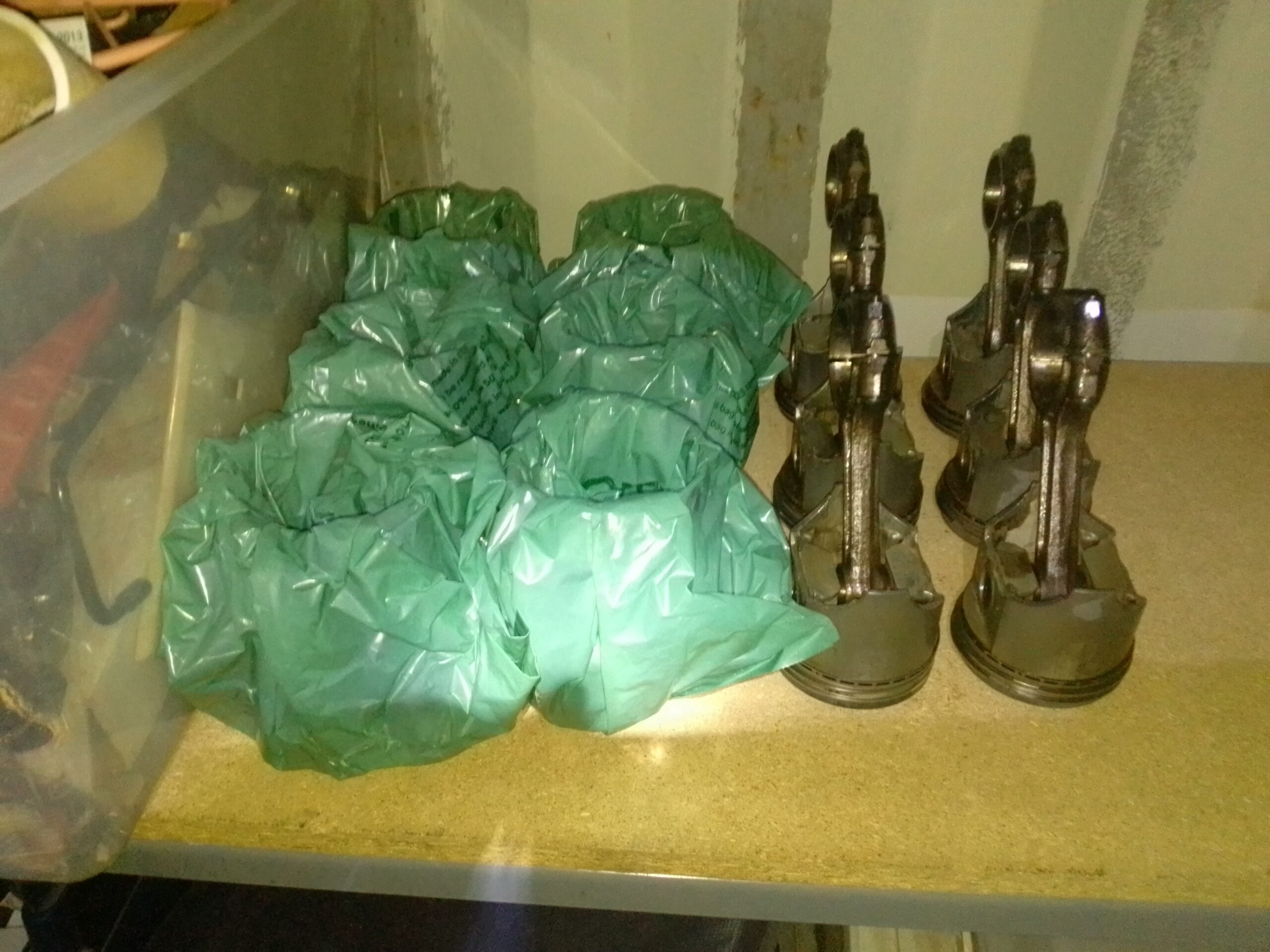
After drying I sprayed everything down with 2-26 lube and wrapped the cylinders with grocery bags. Cores all ready to ship to Clark’s:
Pistons, rods, and cylinders ready for core
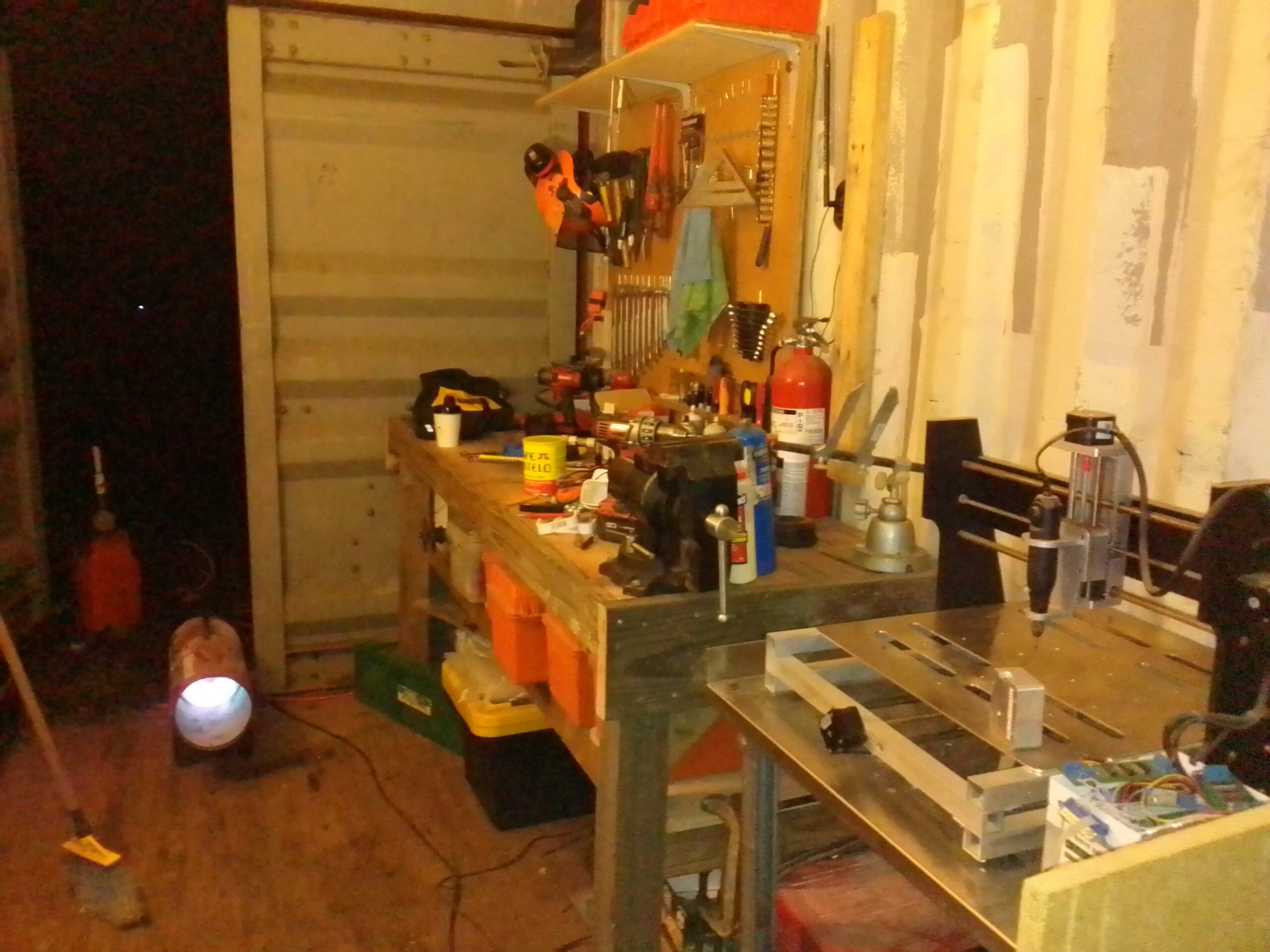
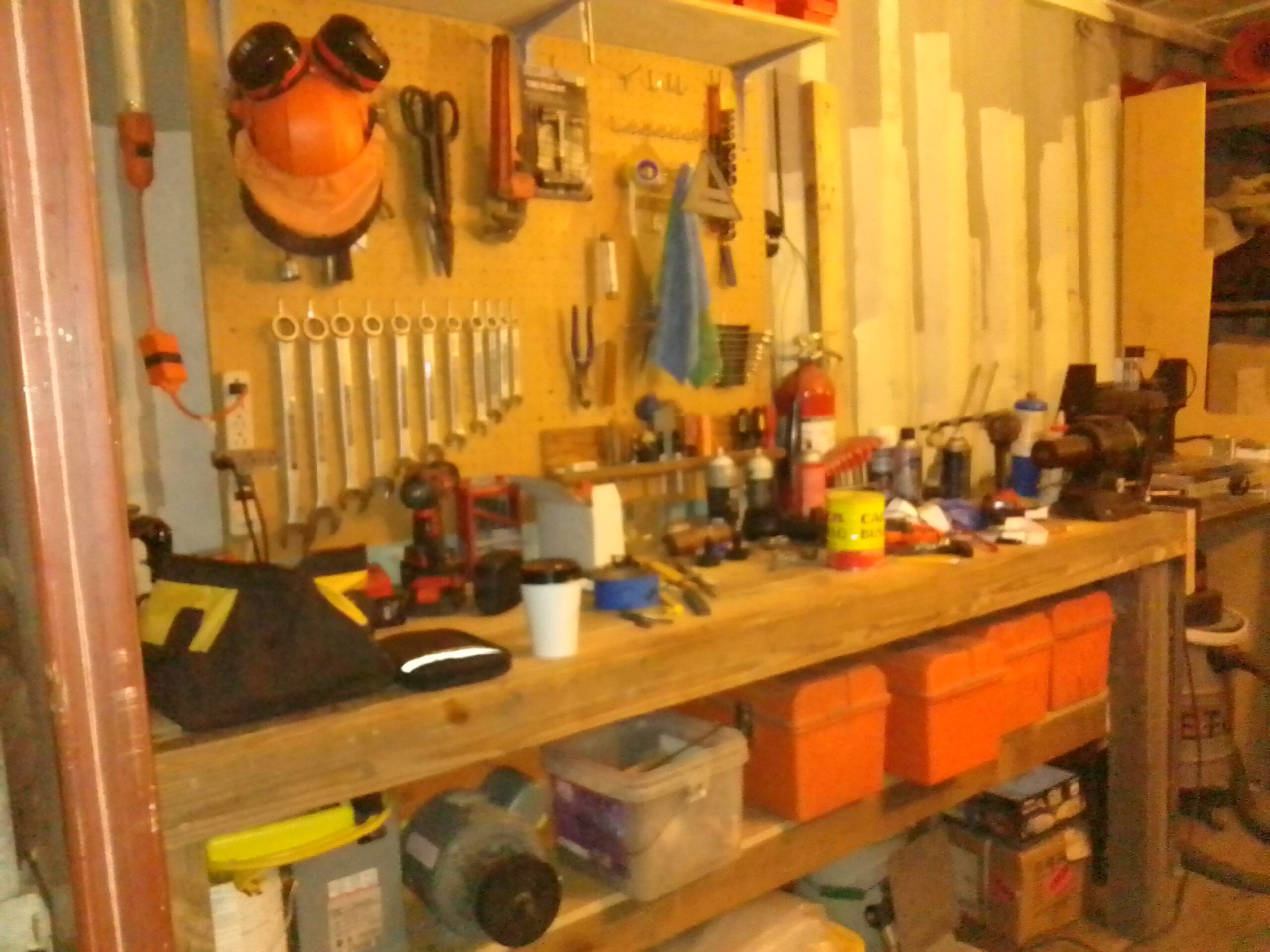
As I impatiently await the arrival of parts, the shop continues to improve:
WorkbenchPegboard and workbench in progress
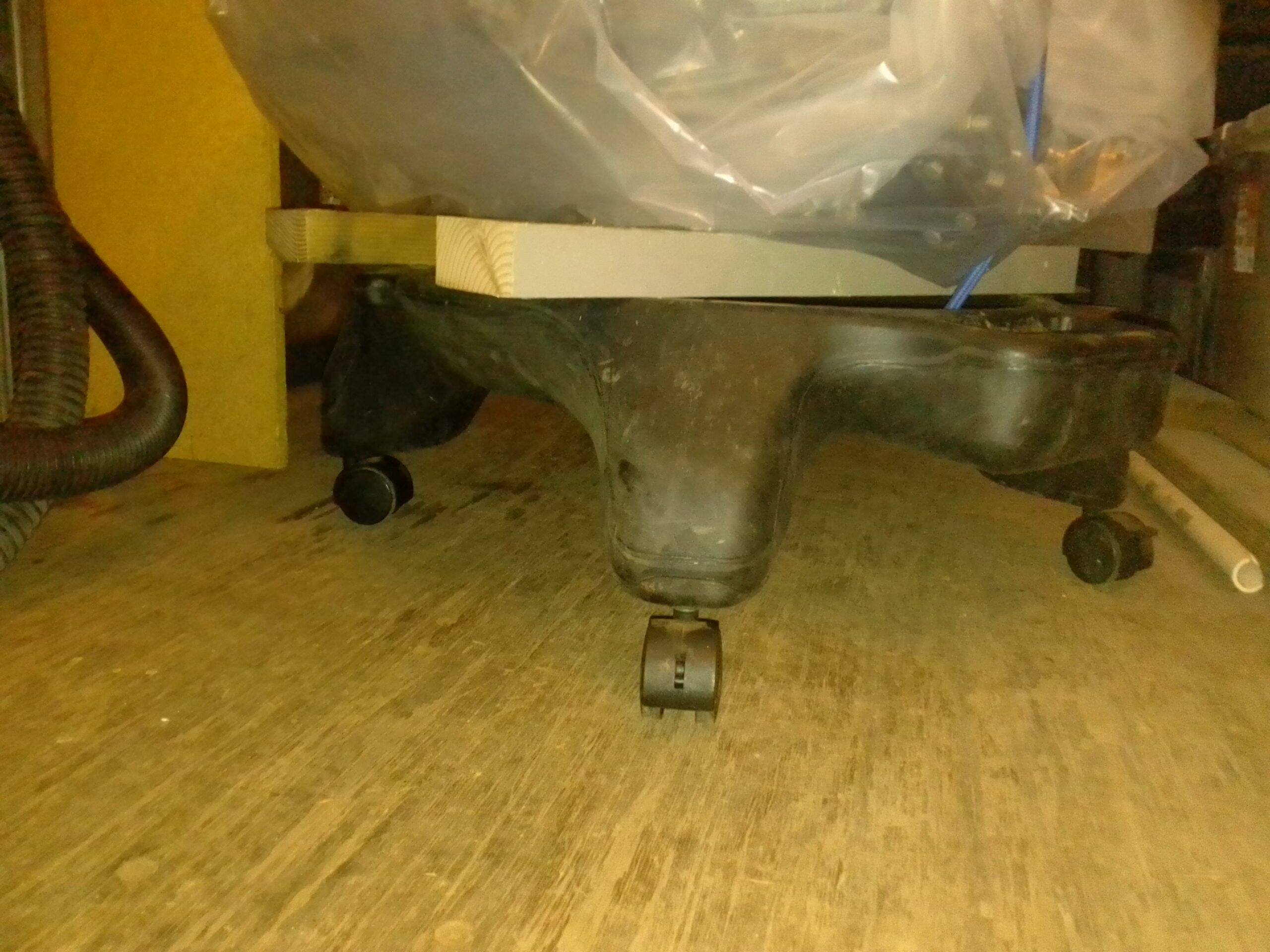
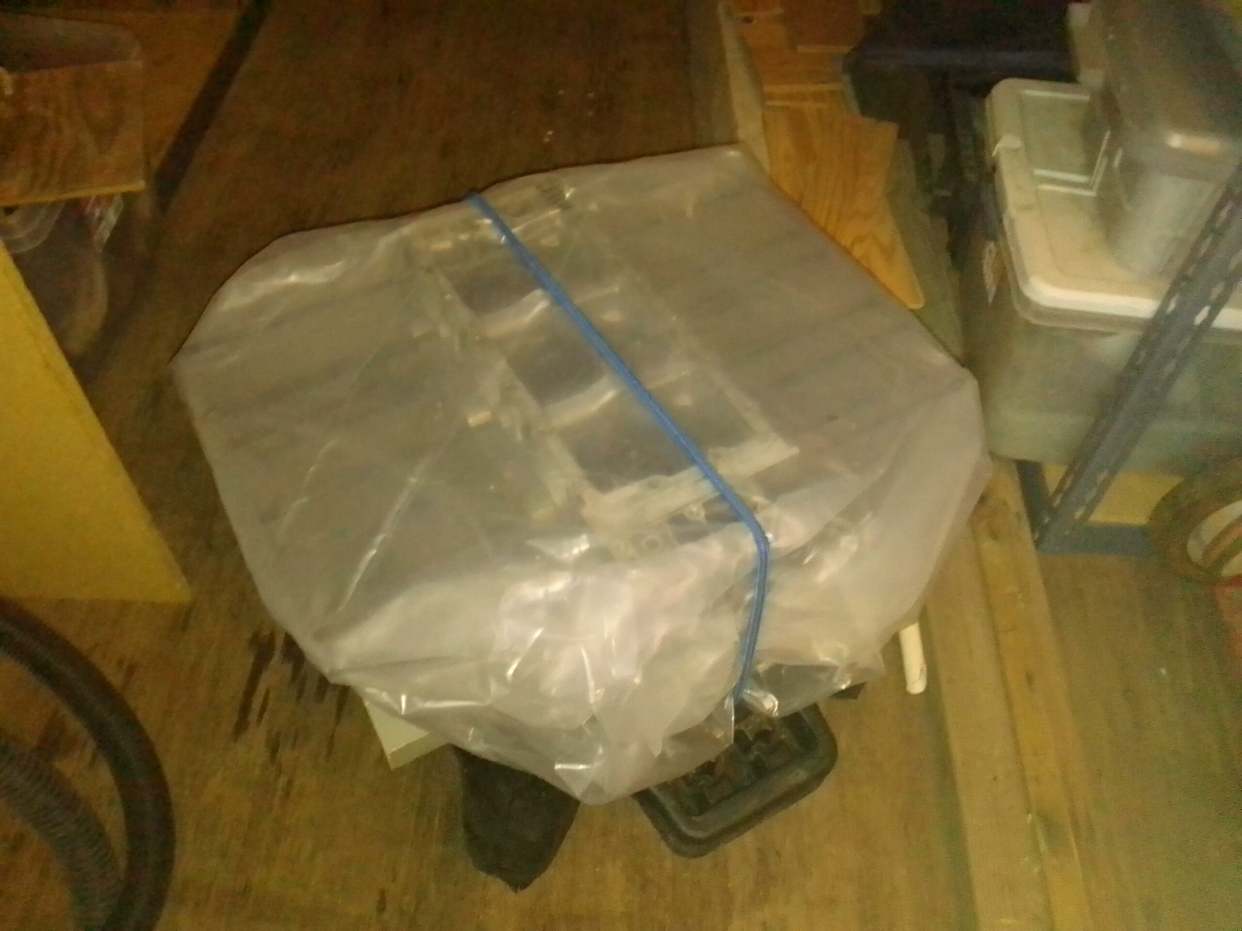
Finally I needed to make it easy to move my engine around. I used the base off of an old office chair to make an engine dolly. I just screwed some 2×4’s to the base. Works great:
Old office chair converted to engine dollyShort block prepped and wrapped for core
That’s all for today. Initial goodies from Aircraft Spruce are on the way so stay tuned!!!
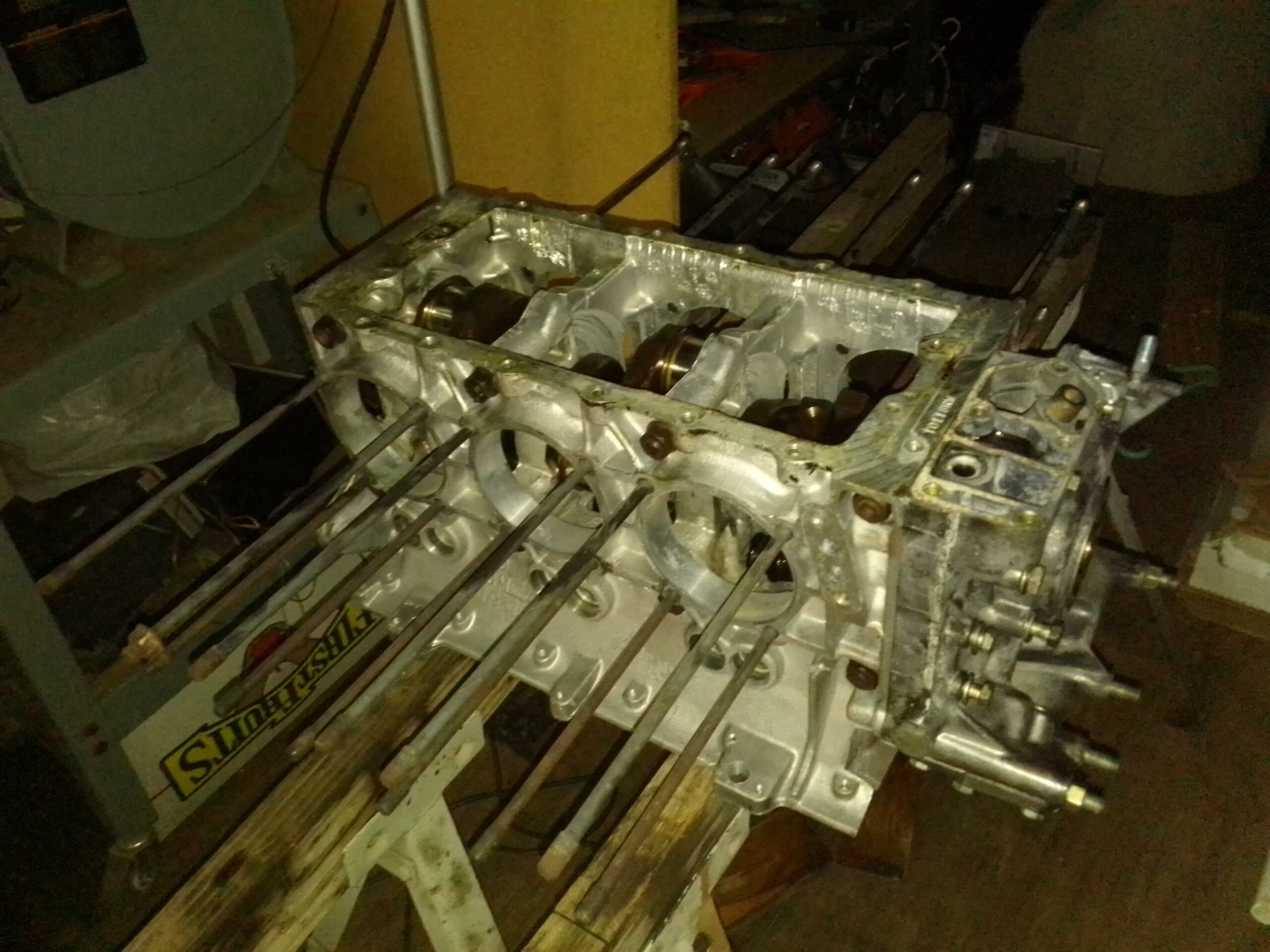
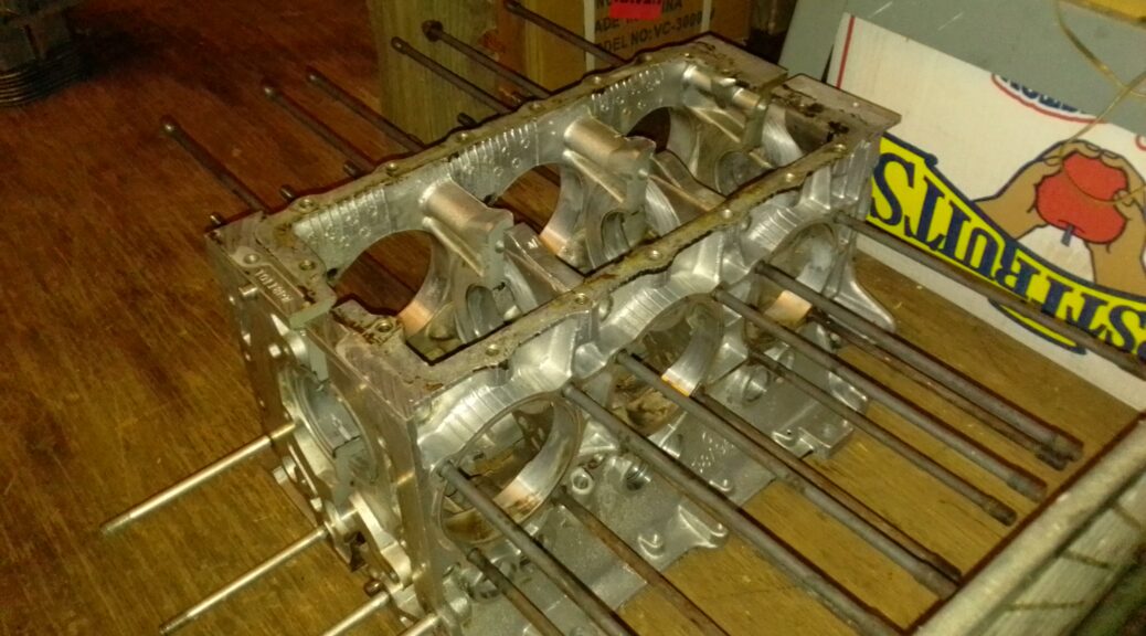
I have ordered the short block assembly, top cover, distributor, and the rear starter/alternator assembly. It is being built by Bill over at Azalea Aviation in Georgia. I have my “core block” all ready to go, so when my engine arrives I will use that crate to ship my core back. Here is the cleaned and gently assembled core ready for shipping:
Case prepped for rebuild core
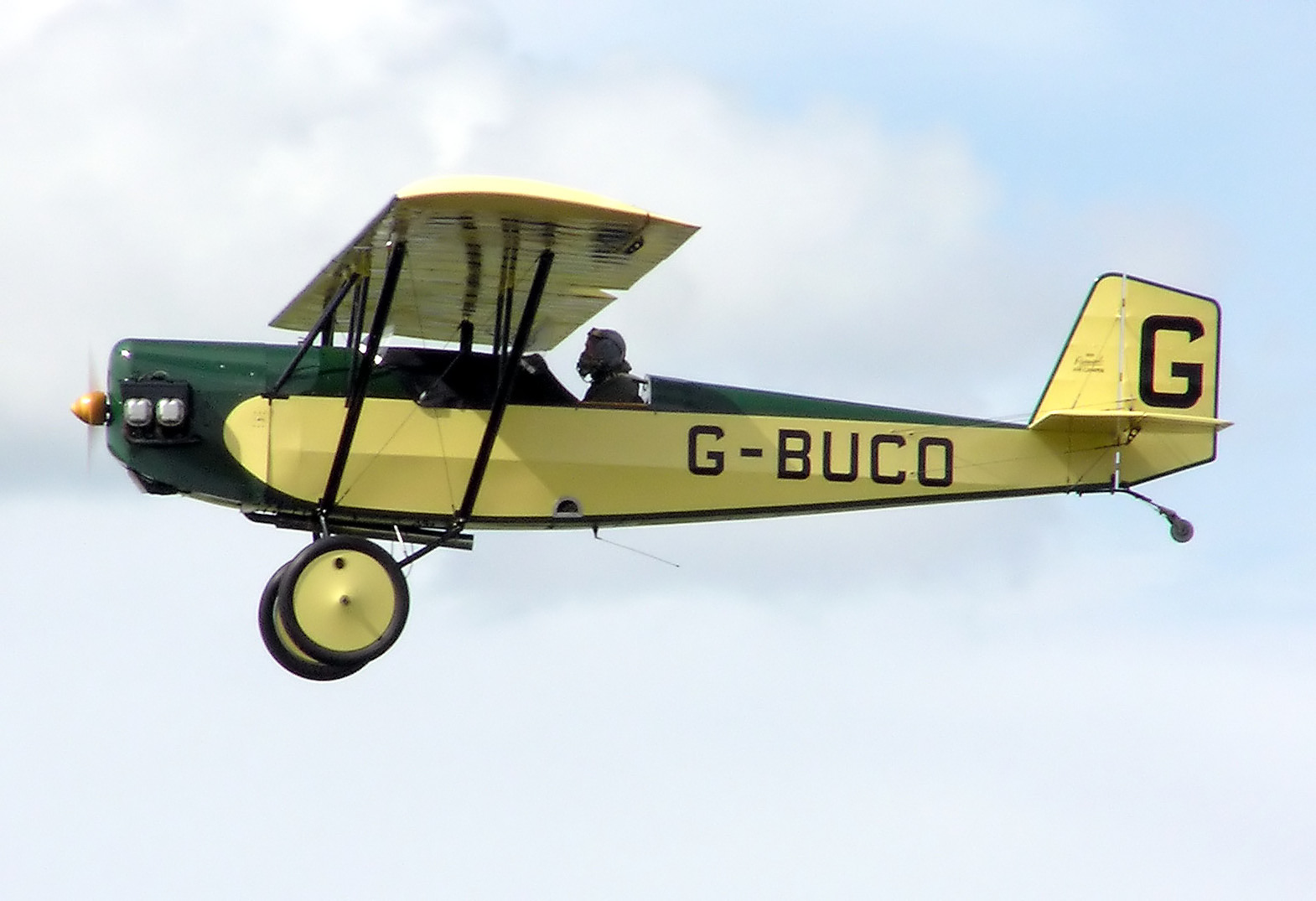
Tomorrow I will be ordering the tail section kits and Pietenpol plans from Aircraft Spruce. Hopefully it will look as cool as Bill’s Piet:
Tomorrow I will also be core prepping my rods and cylinders for Clark’s Corvair. They will provide hardware such balanced rods, cylinders, forged pistons, lifters and gaskets. Bill at Azalea will do the heads and covers for me. Stay Tuned!
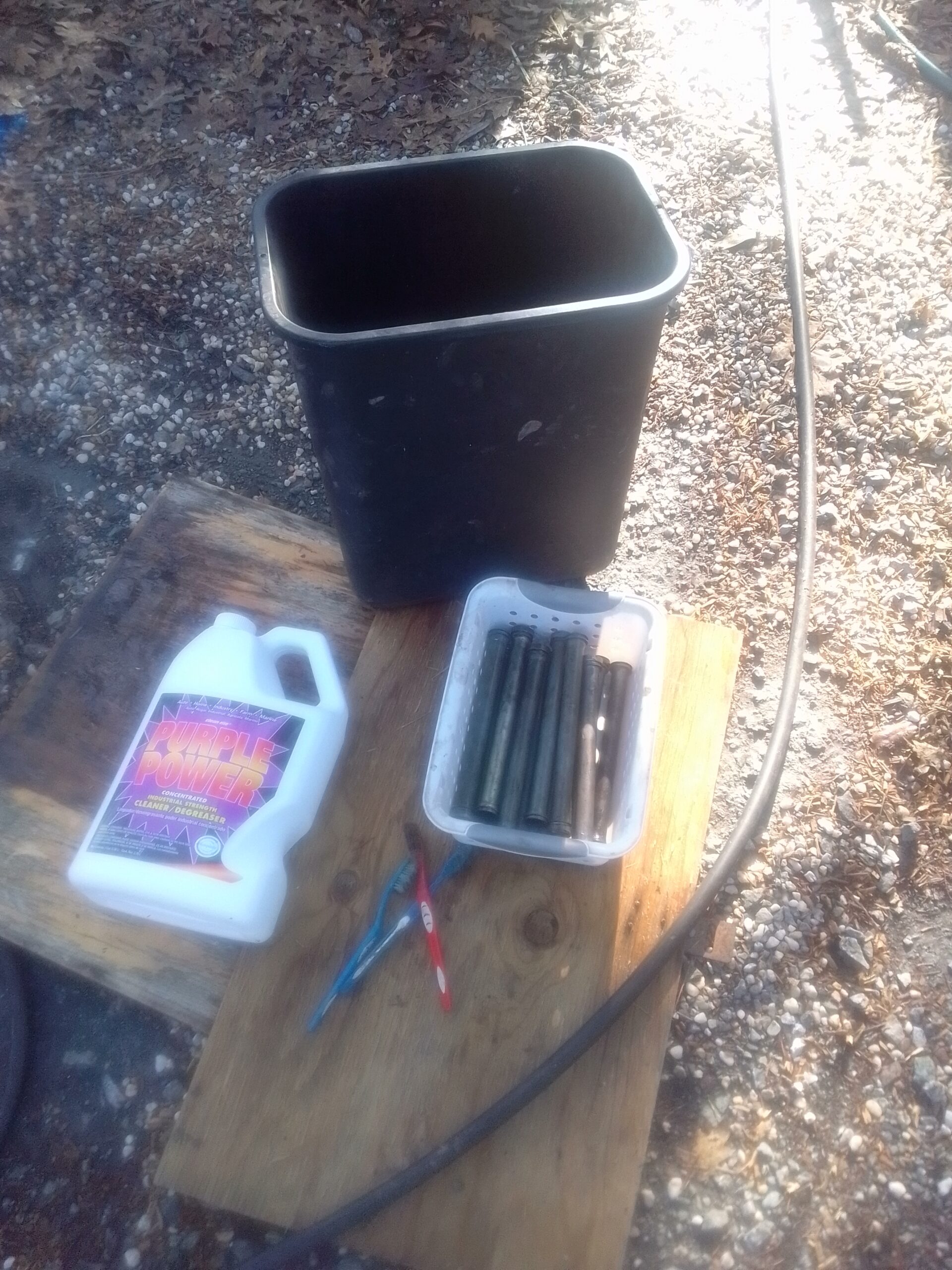
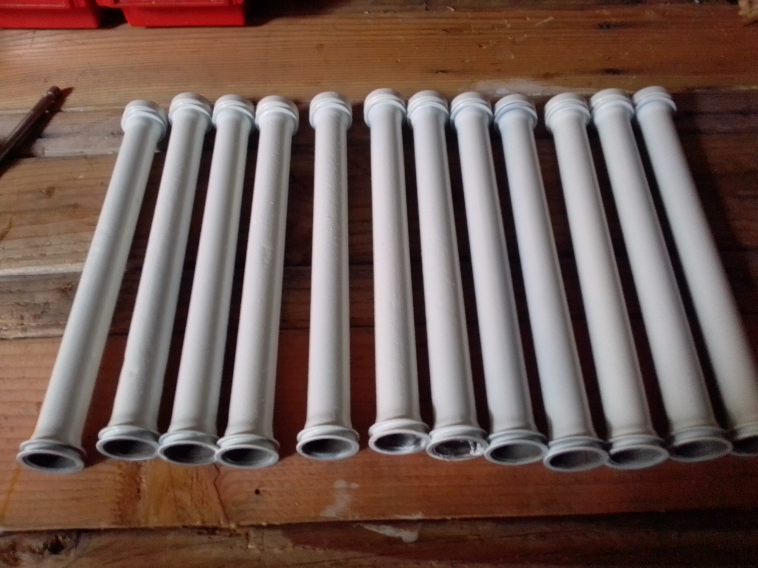
The original push-rod tubes are going to be reused. I was fortunate that all of my tubes were in great condition. Give them a makeover and they will be ready to use.
The Process
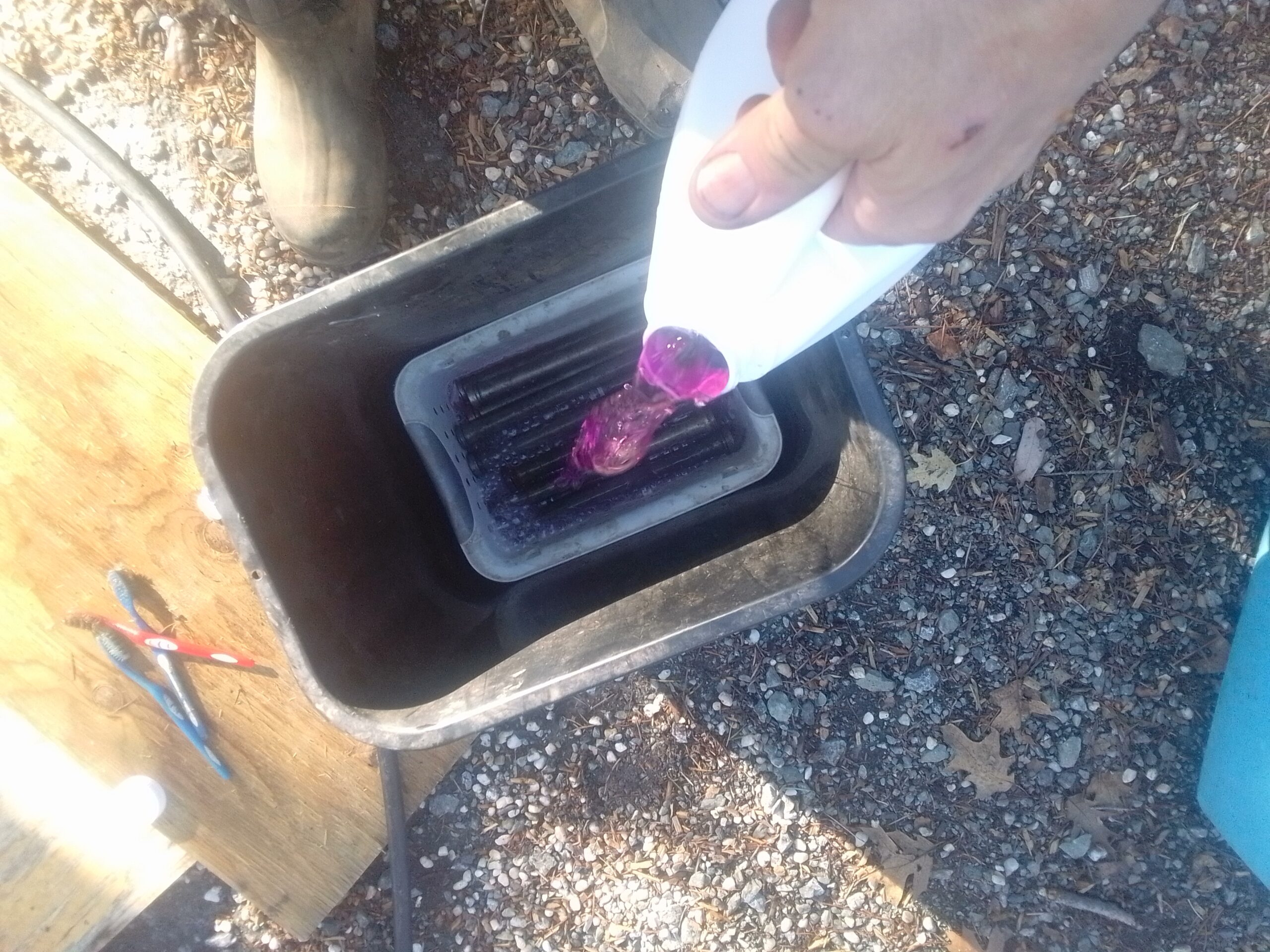
First step is to get them spotlessly clean and set them up to dry. I used Purple Power and hot water to soak them for a few hours.
After soaking I used cheap toothbrushes to clean the inside of the tubes and HFT cleaning brushes to clean the outside. I then stood them up to dry for about 30 minutes.
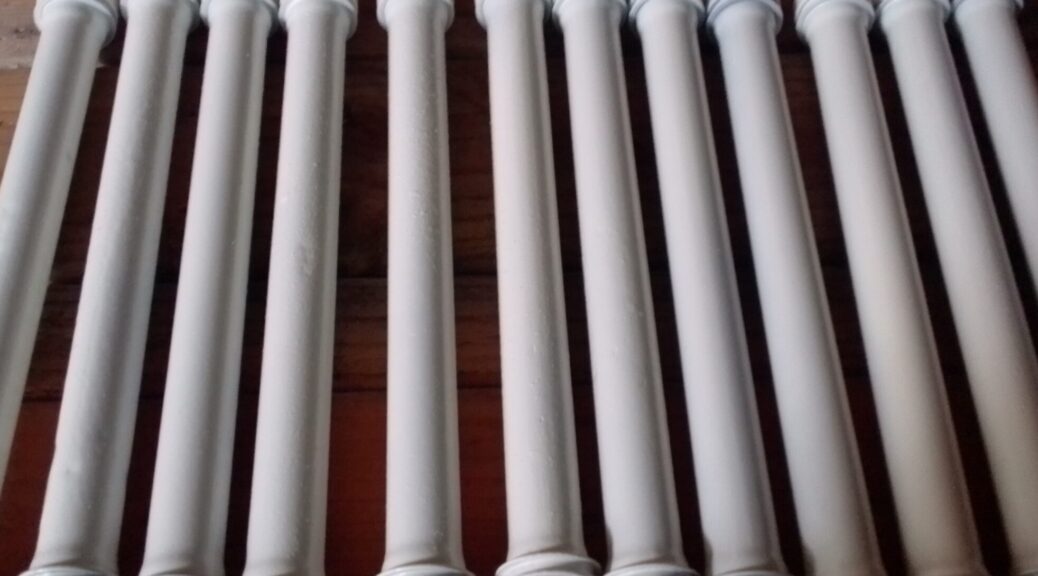
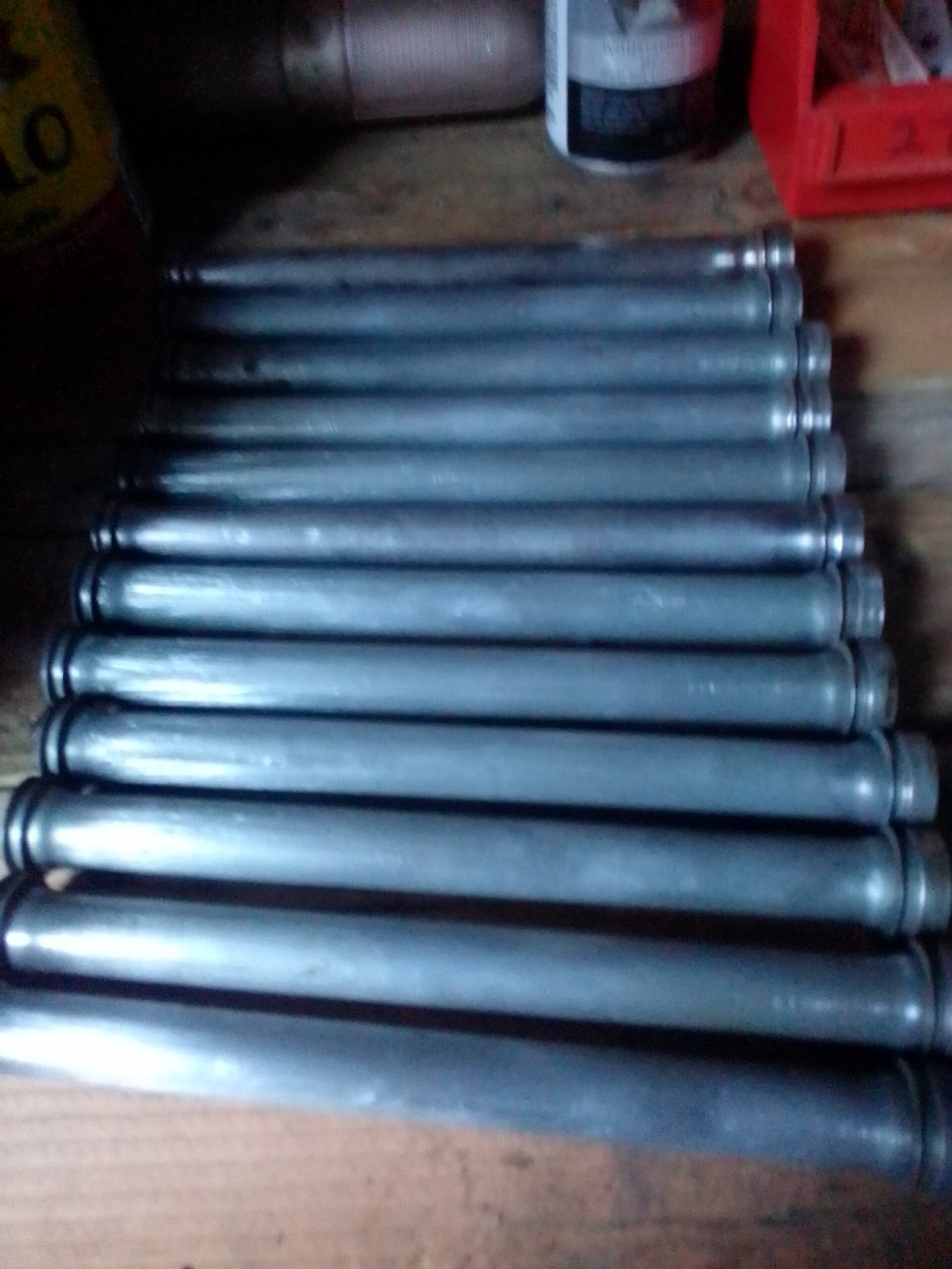
Next I cleaned the tubes inside and out using starting fluid. I then sanded the tubes with 150 grit sandpaper until they were all nice and shiny.
tubes before sandingtubes after sanding
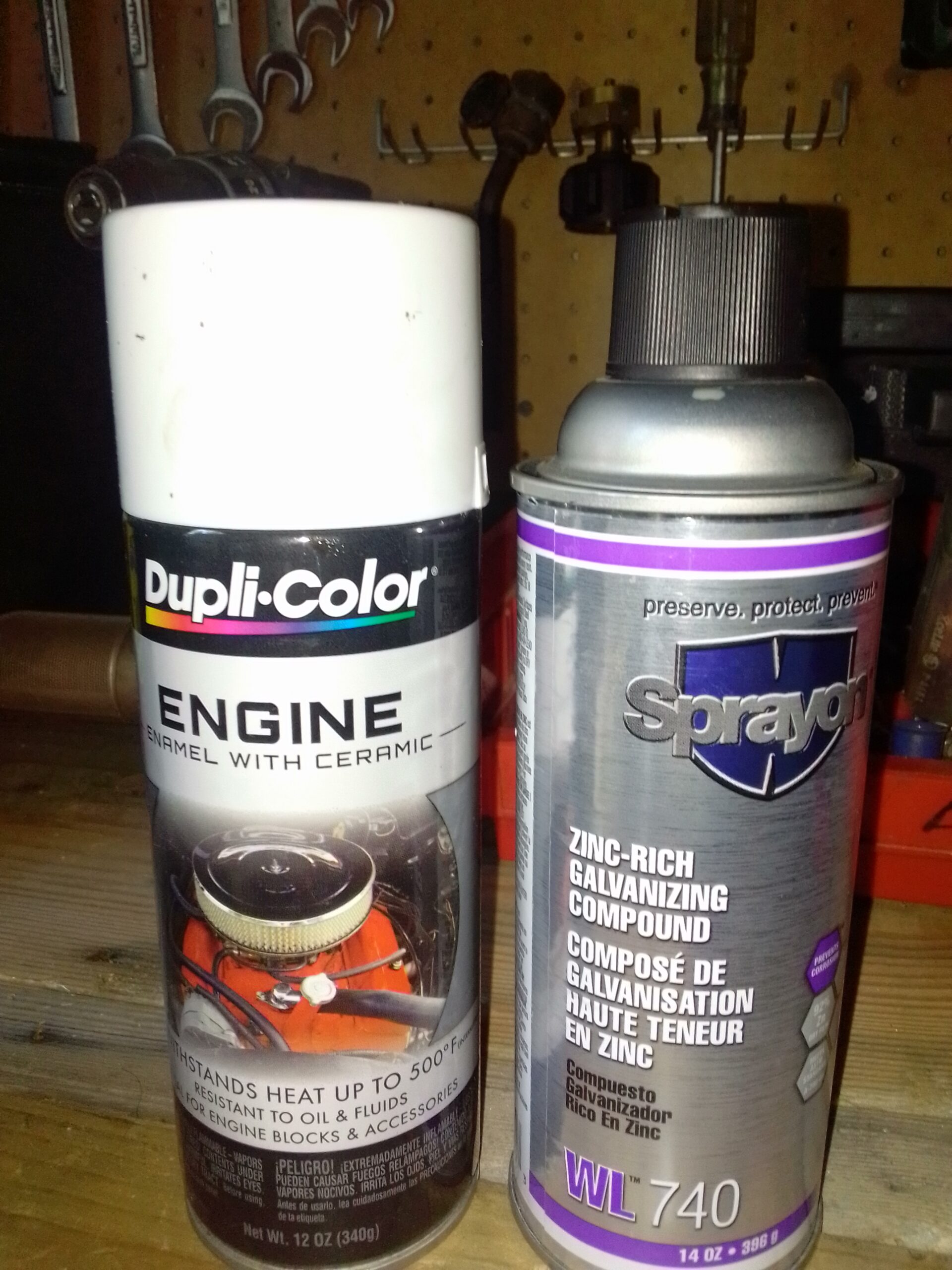
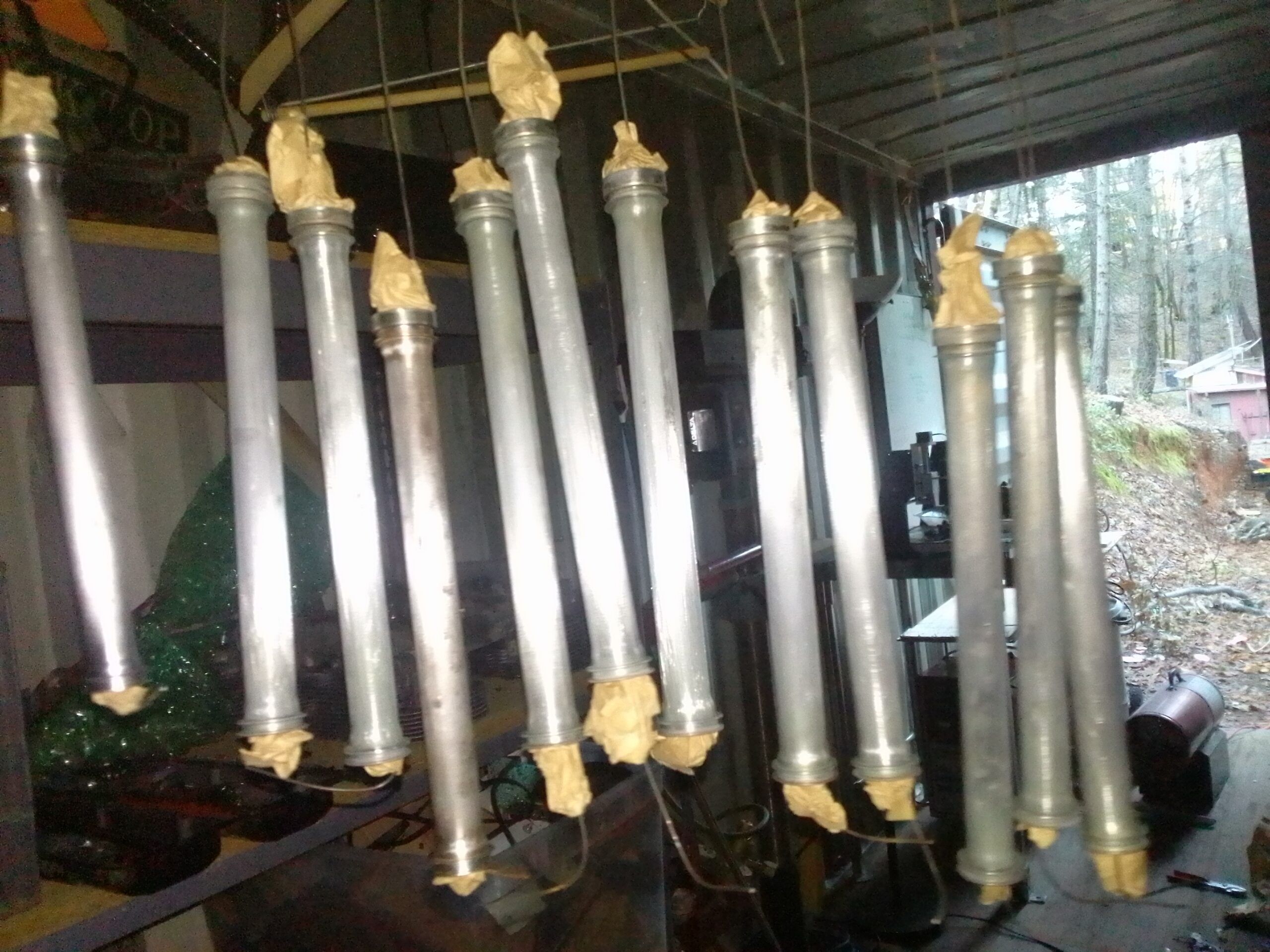
I used high temp zinc primer to prime the tubes then high temp ceramic white to do the final painting.
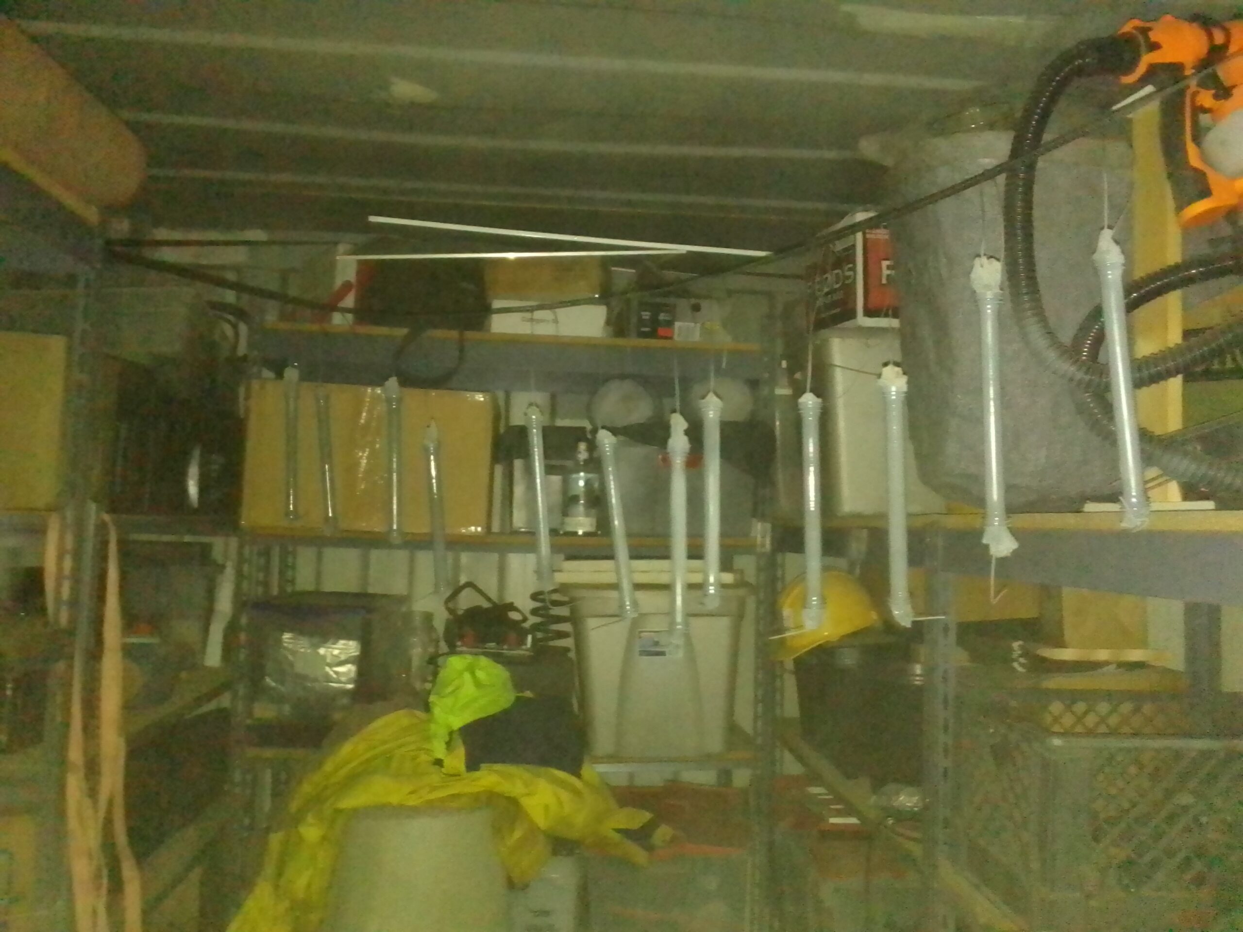
zinc primer and high temp painttubes with bailing wire hangers and paper end plugs ready to primetubes hanging to dryThe finished tubes
These turned out great. Not sure if I need to remove the paint around the seals or if I should leave it. I am sure Bill at Azalea will know. Almost time to order my fuselage kit from Aircraft Spruce. Stay Tuned!
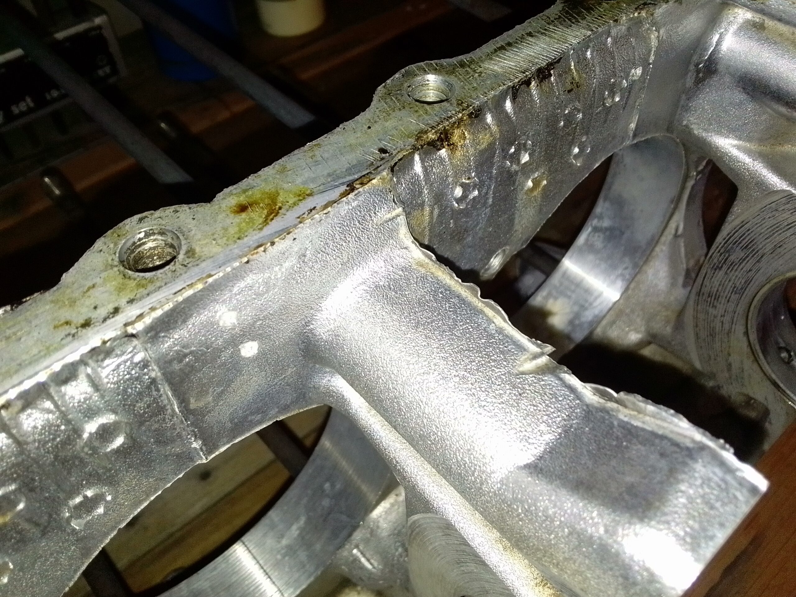
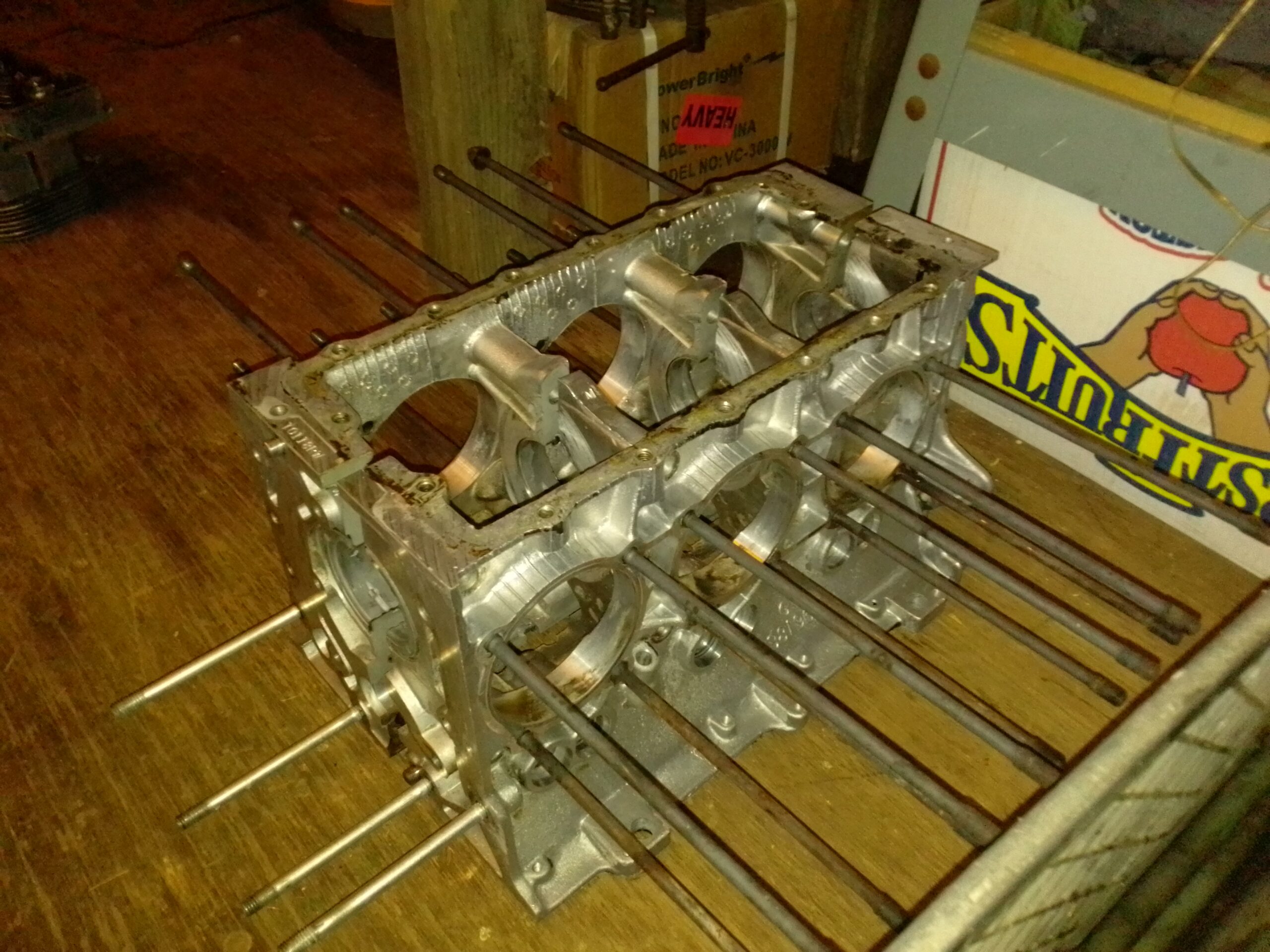
The disassembly and cleaning went very smoothly. To finish the prep on my core for maximum value all the casting burrs need to be removed from the case. The tools that worked the best for me were a straight deburr tip and a wire wheel tip.
Before DeburrAfter Deburr
The purpose of this procedure is twofold. First and foremost, these small extra pieces of aluminum can break off the case and get in the oil and possibly work its way into the motor. YIKES! Second there are sharp edges that will shred your gloves and hands during the detail cleaning process. A deburred case is SO much easier to work on.
Azalea Aviation is doing my Fith Bearing build on the short-block so I will be ordering that today. This means I need to get my oil pump housing prepped for the conversion to a rear alternator/starter setup. This will allow Bill at Azalea to include the alt/start with my block build. Working on my push-rod tubes now. Stay Tuned!
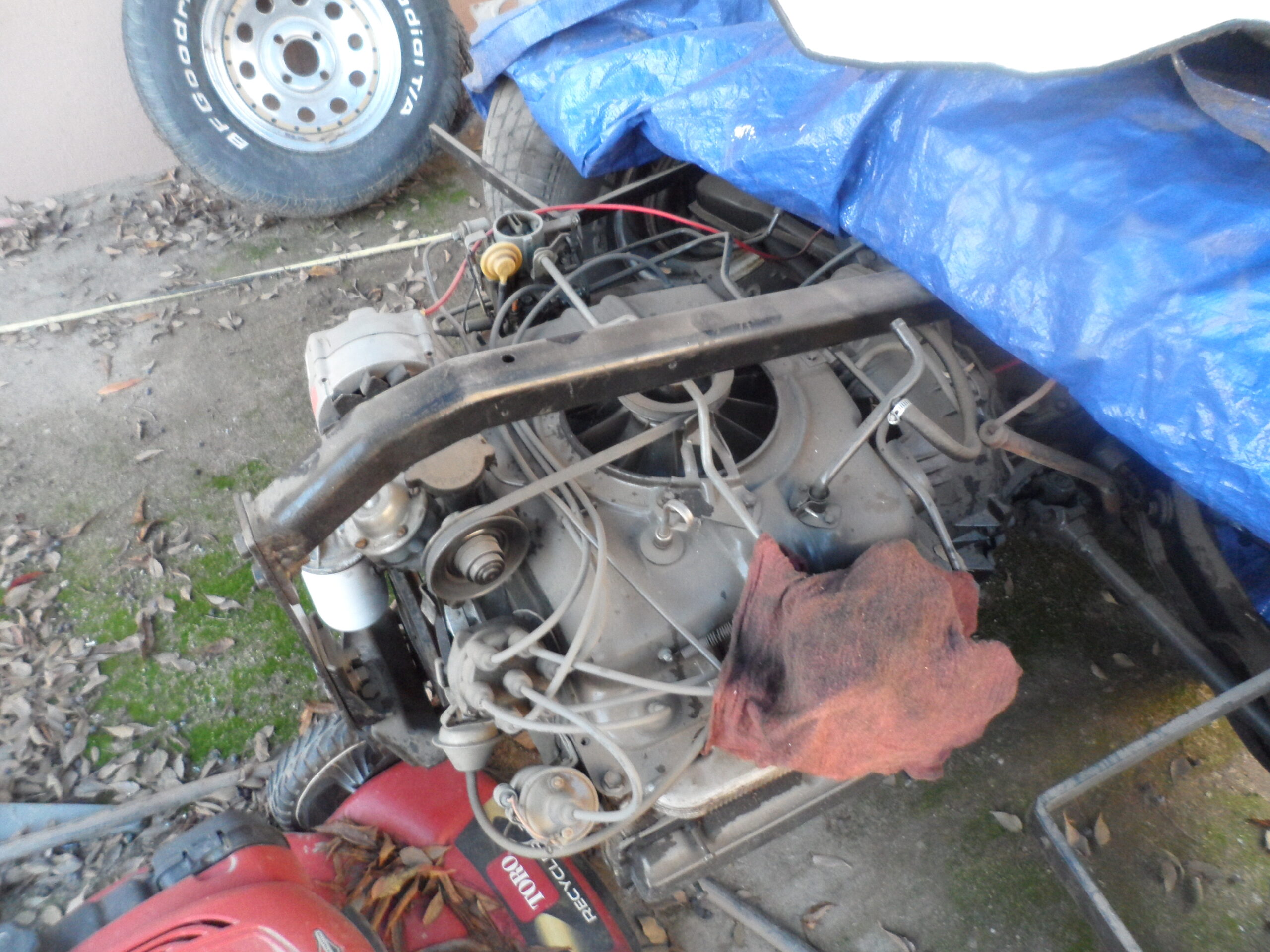
I have begun my airplane building project with the engine. Why? It was the cheapest and easiest part to acquire so I could begin my build immediately. This also leaves open the option to build something other than the Air Camper if I happen to change my mind.
I got pretty lucky on the Corvair engine core. It was very clean and in good shape.
It has most of the core parts needed for the conversion. I think everything except the distributor was included for $400. It had been mounted on a trike and a prop boat before that and was very clean. I found a distributor for that core on eBay for $50 after shipping.
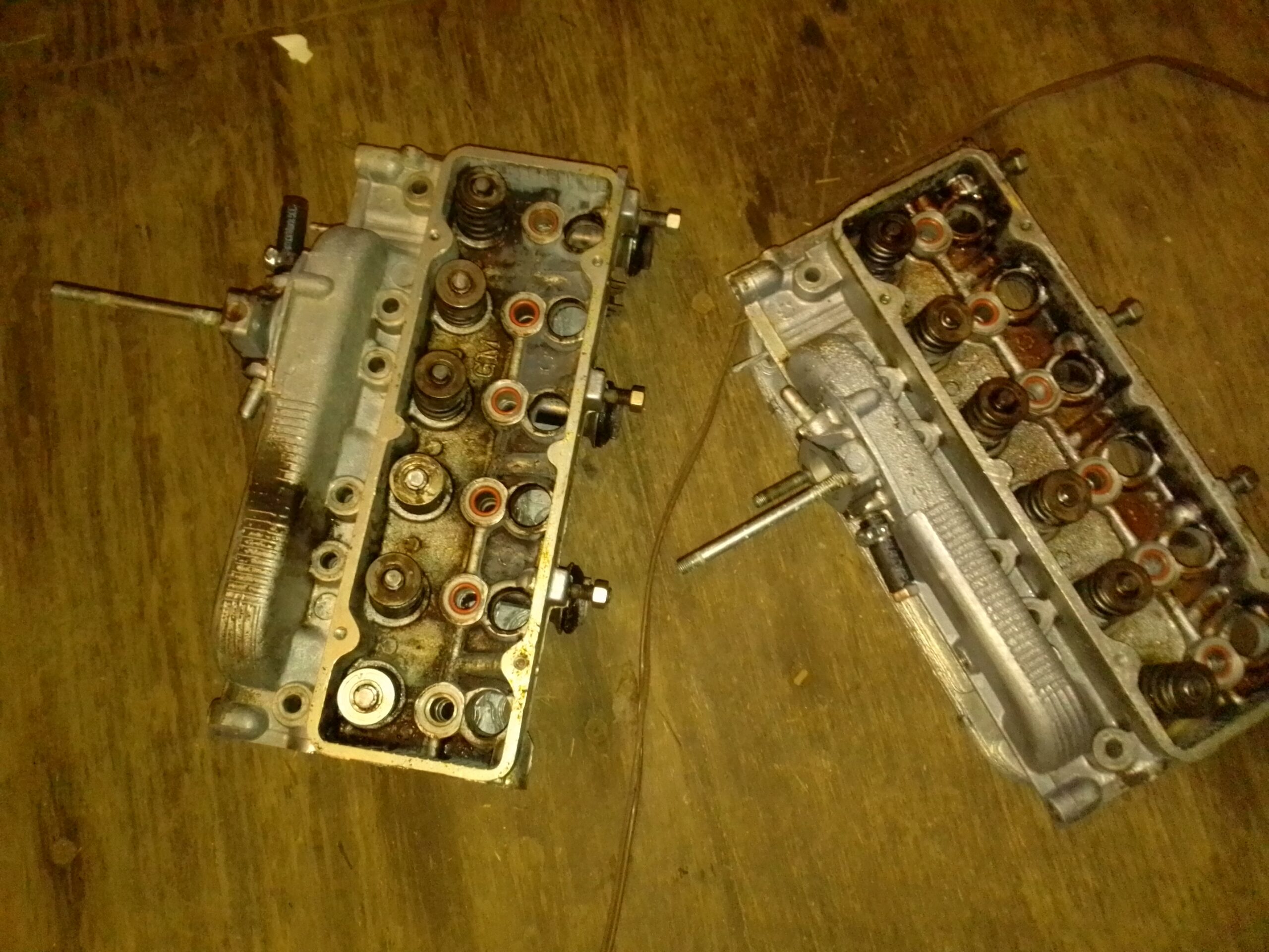
The only caveat was that the heads were “smog heads”. These are unfortunately not suitable for aircraft build. However, it looks like Azalea Aircraft may still be able to accept them for core value. More on that when I get to it.
Heads are almost ready to send in for core value.
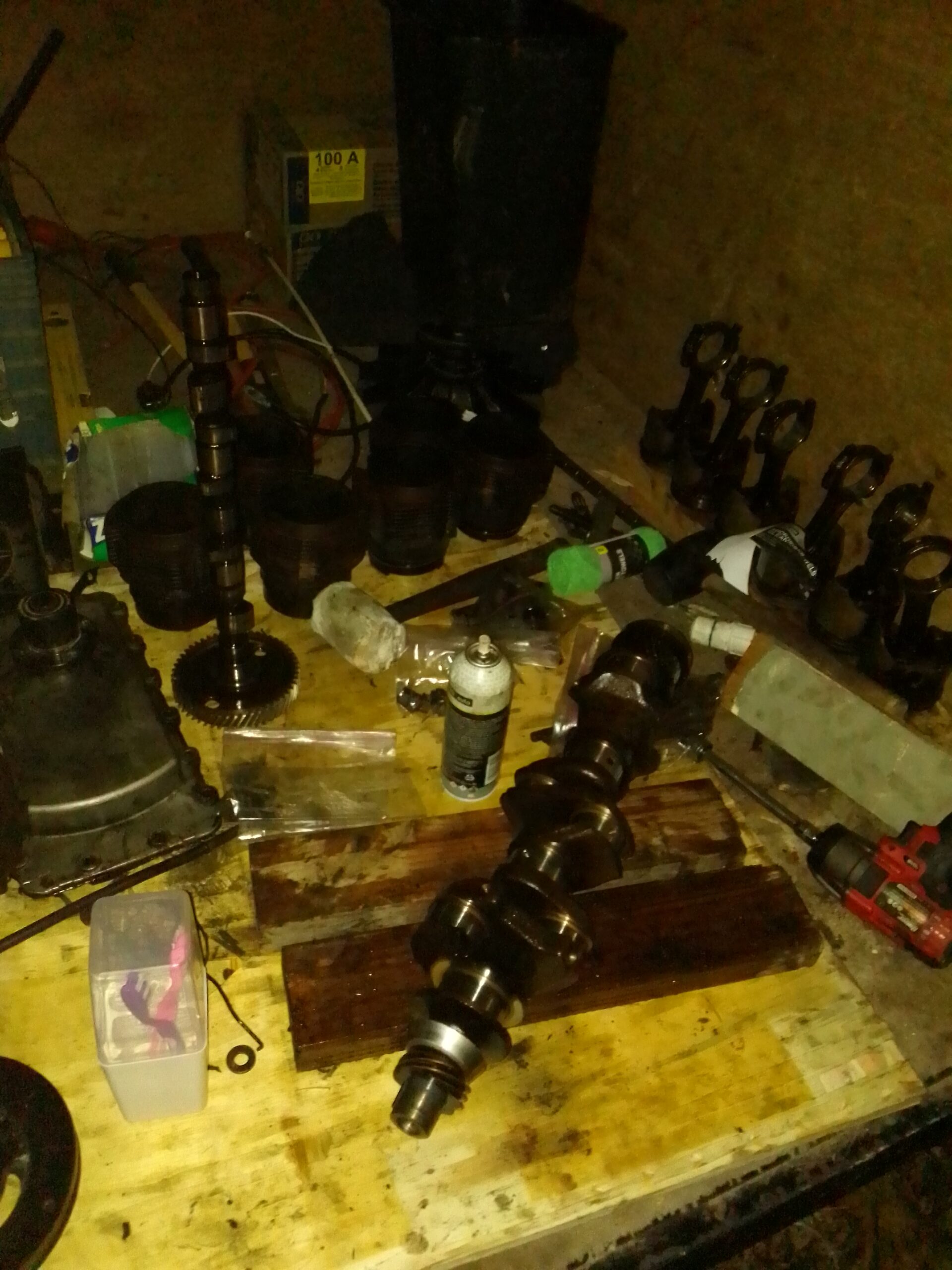
The disassembly went quite easily and took me a little more than a day. Here are some of the parts almost ready to be packed and shipped out for processing:
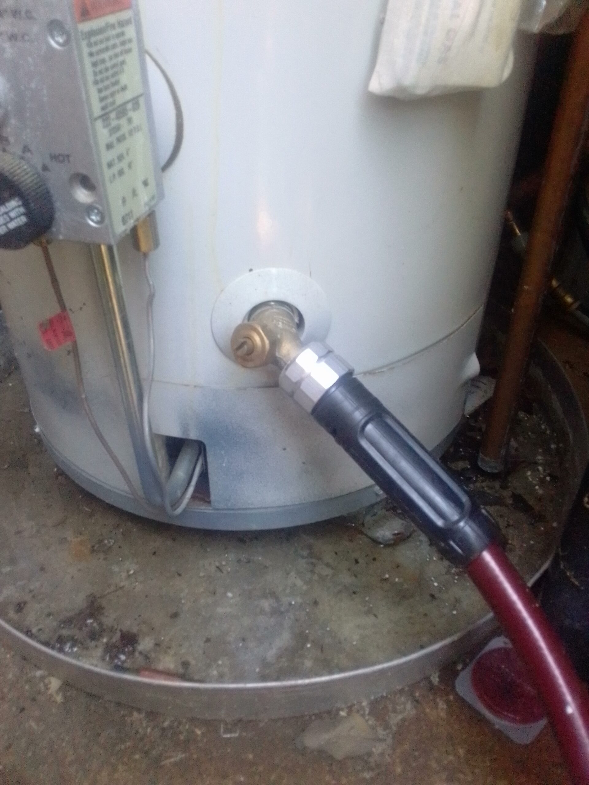
The first thing to build is the short block and Integrated Fifth Bearing. I used Purple Power ($6.50 per gallon at Dollar General) and a pressure washer hooked up to my hot water heater. Using hot water with the pressure washer is highly effective. I will deburr and detail clean the case in the next article. Stay tuned!
Becoming a pilot has always been a life dream. However, it is anything but cheap. This has always been my major setback.
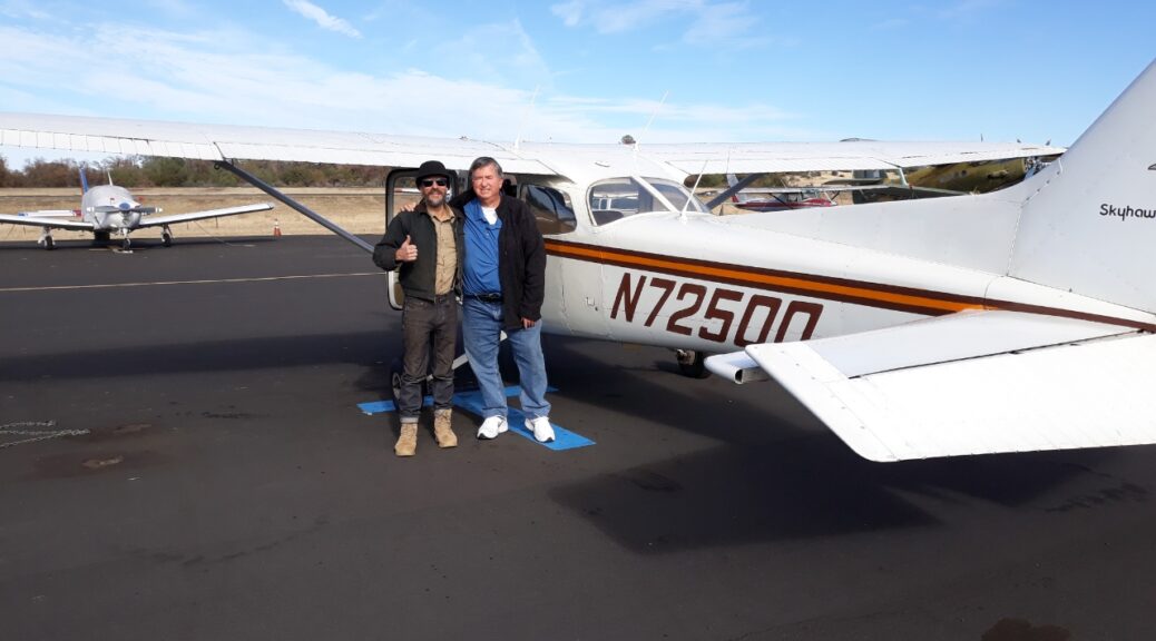
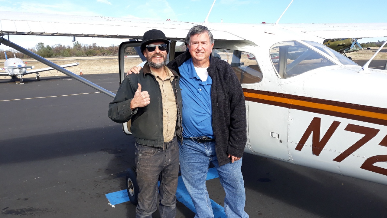
A couple of weeks ago my friend Al from my ham radio club took me flying in his Cessna 172. All I can think about anymore is flying. What to do???
The solution is quite obvious. I need to build an airplane!
So far I have begun the work converting a Corvair engine for aircraft use. This engine will be going in a Pietenpol Air Camper. I will be blogging and YouTubeing throughout the entire process. All posts related to this project will be available through the “Aircraft” tab in the upper right hand side of the page. Check out the following links to learn more:
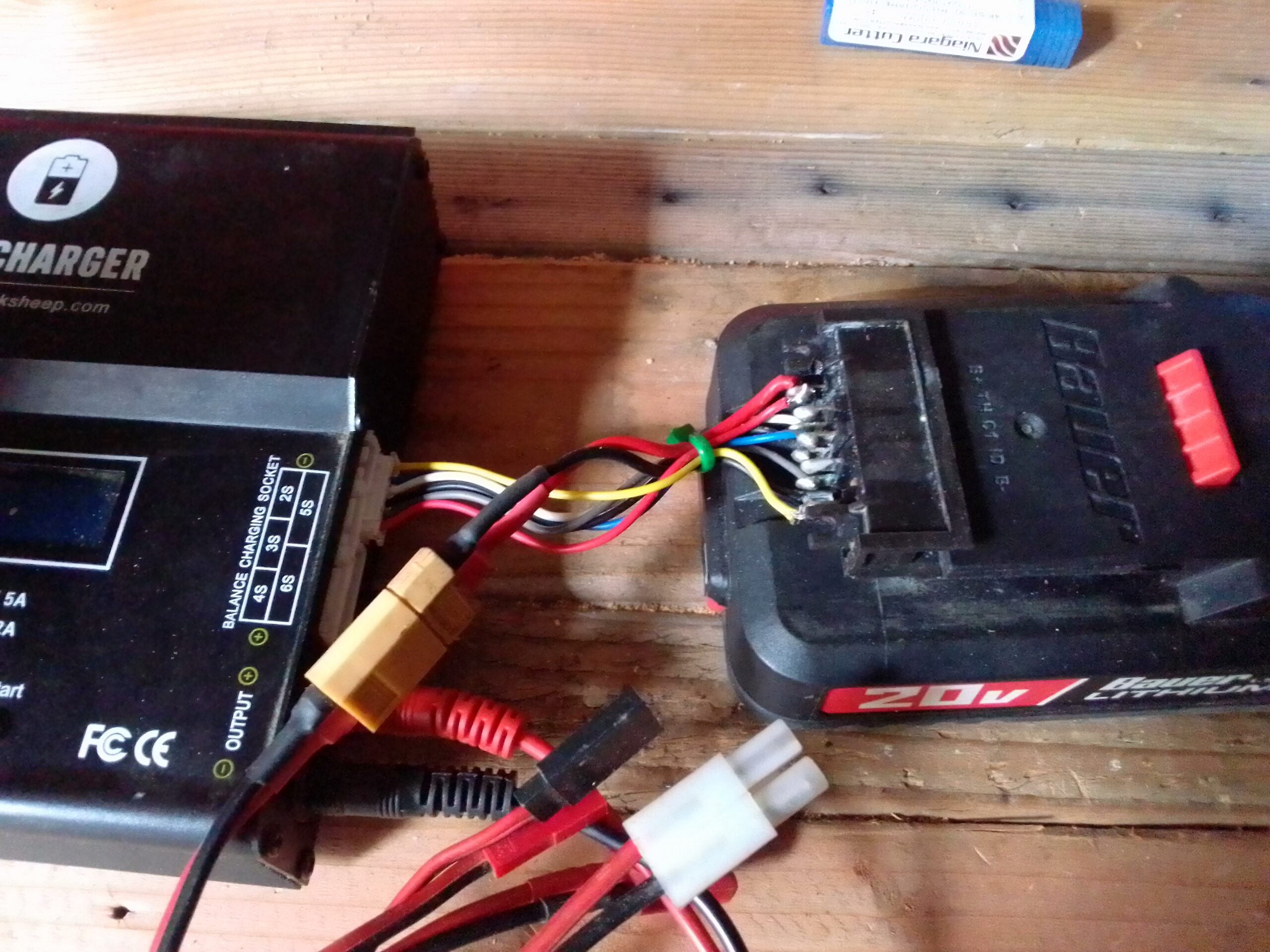
This all started the other morning when I realized I had left my Bauer battery pack and charger outside in the rain. Long story short you can use the plug from a broken charger to make an adapter to charge your battery packs with a RC Vehicle Balance Charger.
Bauer 20v Pack Connected to Balance Charger
The Story
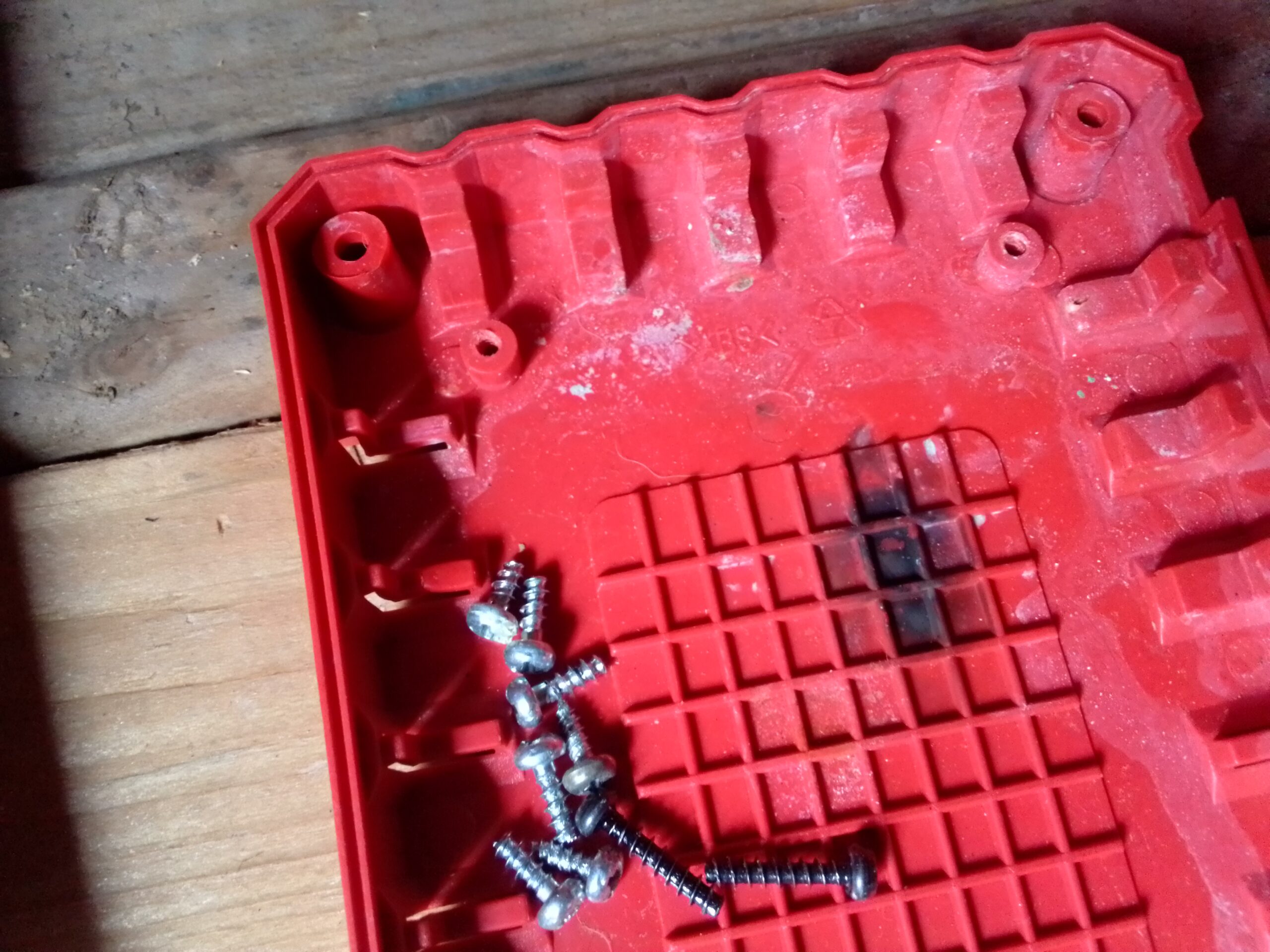
After sitting, plugged in, in the rain, overnight, there was a large amount of blue material on the battery and charger connections.
Pushing the button on the battery showed full charge, so I cleaned off the connections and tried it in my drill. No dice. I dissembled the battery pack by removing the four torx screws on the bottom. There was corrosion on the inside of the connector but everything else looked OK. I cleaned off the connectors from the inside and reassembled the battery. JOY! The battery is working again.
Things were not so good for the charger. Under the charging board there was a huge black spot where a bank of resistors had fried.
Magic Smoke Stain
I was thinking about repairing it when I noticed that the plug part inside the charger was a self contained unit. Not only that, the connection plug for the sense port was the same as the plugs on the batteries for LiPo RC batteries (eg Drone Batteries).
The pin-out on the above mentioned plug is not the same as a standard RC LiPo battery, but all the necessary components (and then some) are. If you are looking at the balance plug (on a Drone Battery for example) with the bumps facing down, the leftmost wire is ground and the next wire to the right is the voltage of one cell. The third wire is the voltage of two cells, the fourth wire is the voltage of three cells and so on depending on how many cells you have.
The Hack
In a nutshell we need to make the Bauer battery pin-out match a stander RC Lipo Battery. The finished adapter will look something like this:
Bauer Adapter Dongle
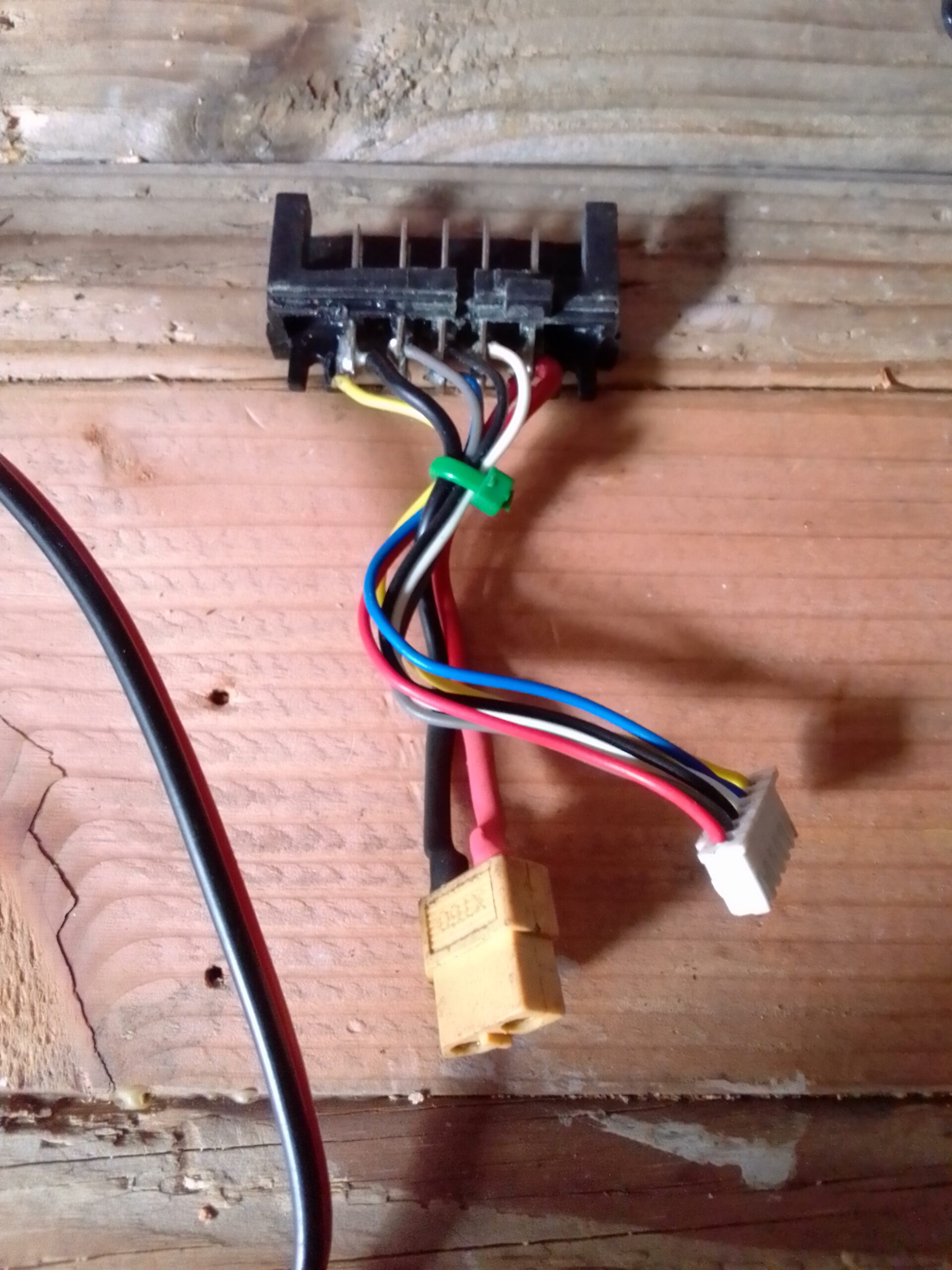
You will need security torx bits (with holes in the middle) to remove the bottom plate from the charger. Then just unscrew all the Philips screws until you have just the battery plug unit. Unplug the 6 wire plug from the board and cut the red and black wires as close to the board as possible.
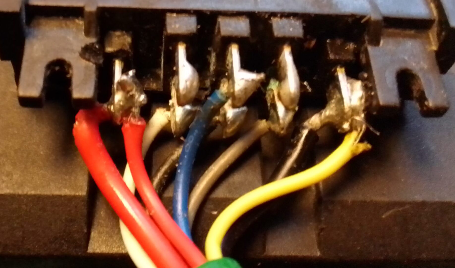
Using a small screwdriver to press down the tabs, remove the pins from the 6 pin plug (they need to be rearranged). The small yellow and red wires (that you just pulled from the plug) are for the battery’s internal temperature sensor, we don’t need to monitor this sensor so we can use these wires to finish our plug. De-solder the small yellow wire and solder it with the main negative (big black wire). De-solder the small red wire and solder to the main positive (big red wire).
Move small red wire to big red wire post. Move yellow wire to big black wire post.
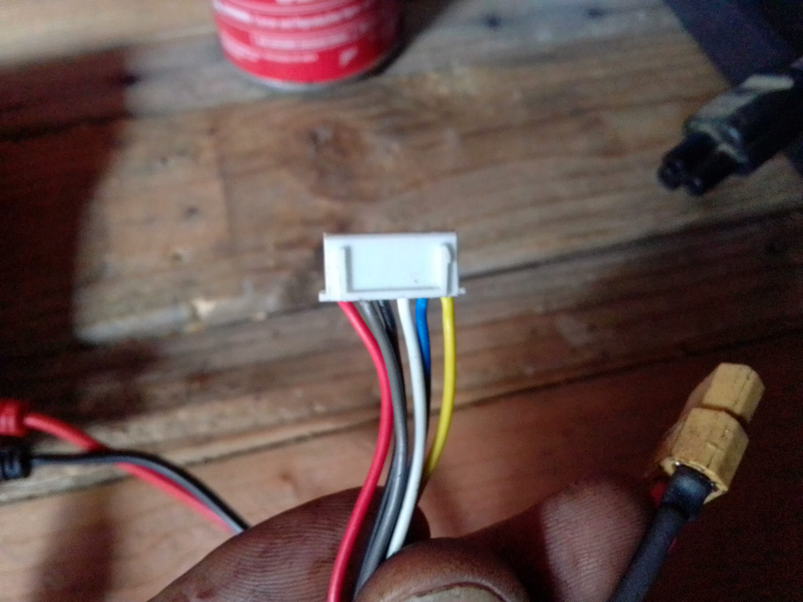
Solder a battery connector (salvaged from old battery pack) to the main positive and negative (big wires). Finally reinsert the pins into the plug as pictured:
Bumps Up: Red, Grey, Black, White, Blue, Yellow
The adapter is finished and just needs to be tested. Plug the adapter into your Bauer battery pack. Using a volt meter your battery plug should show about 20v. With the bumps facing down your 6 pin plug should test as follows (voltages are approximate and will vary depending on the level of charge):
Yellow: (-V)
Blue: (+3.7)
White: (+7.4)
Black: (+11)
Grey: (+14.7)
Red: (+18.4)
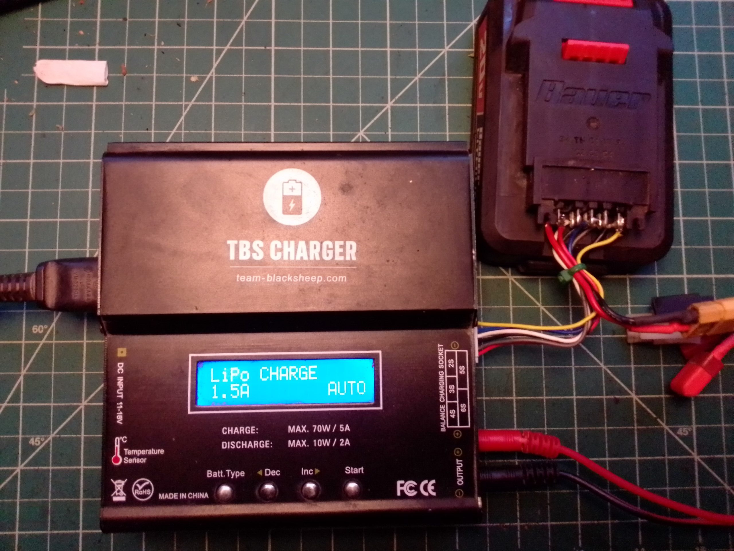
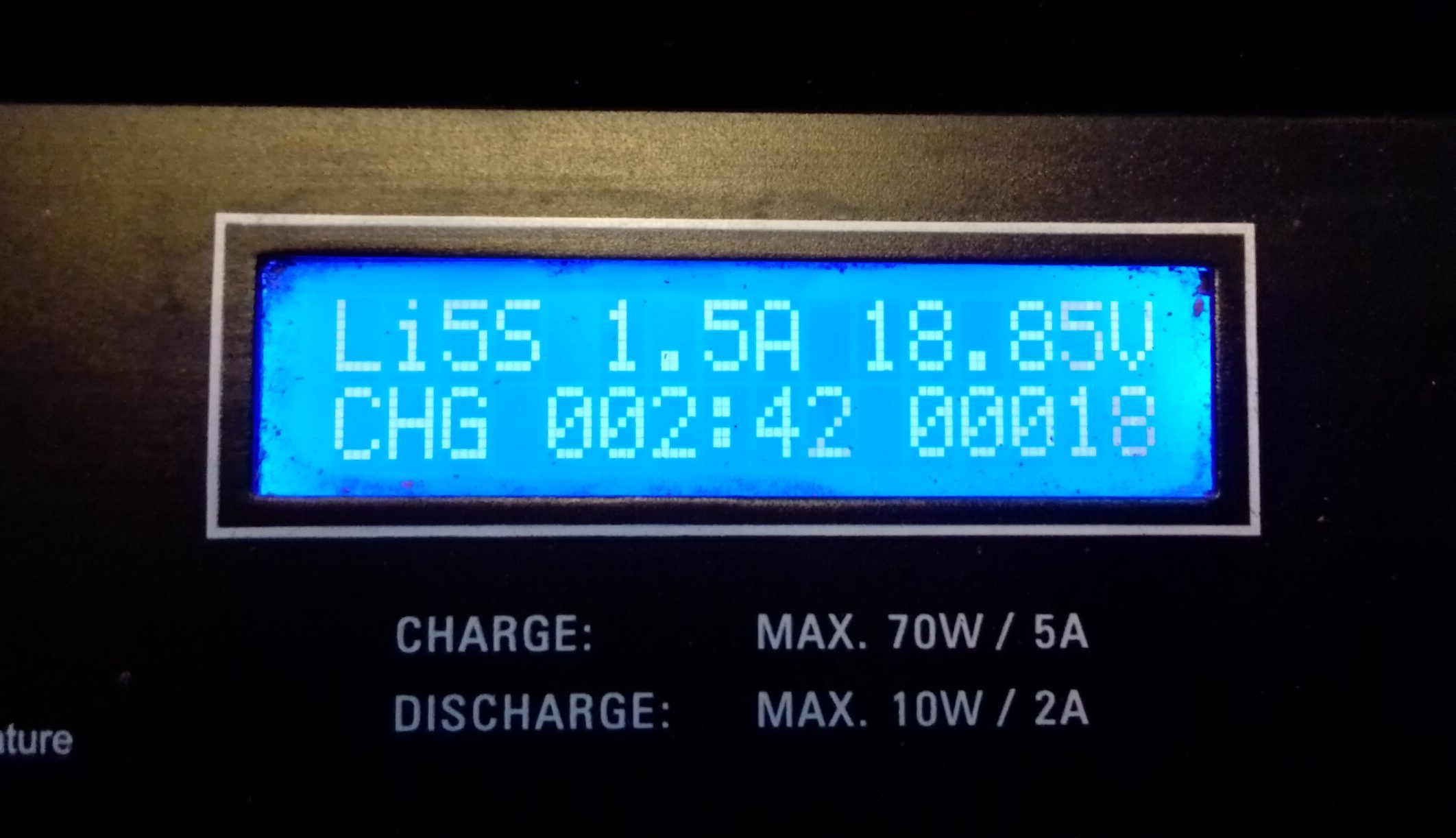
Using the adapter you can now connect and charge your Bauer tool packs. In the program mode set your battery type to 3.7V (Lithium Poly or LiPo). Set the amperage to match the AH listed on the side of the battery pack. The charger will auto-detect the number of cells (5) and after doing a quick balance on the cells will charge the pack until full.
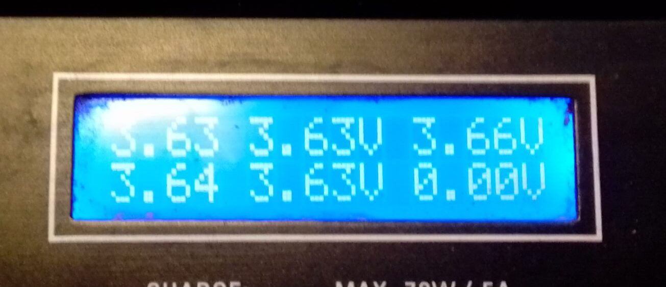
LiPo Charge, AutoCharging in full swingIndividual Cell Voltages and Balance Charging
In summary, this hack is very simple and could be considered an upgrade to the charger from HFT. Having the info display showing the voltage of each cell and balance charge mode are both great. There is also a fast charge that I haven’t tried, but this already charges my batteries quicker and more completely than the Bauer charger.
If you enjoy my articles, please consider visiting my sponsors links or subscribing to my YouTube channel. Thanks!!!
Off-Grid Sustainable Living & Life Hacking – DIY or DIE!