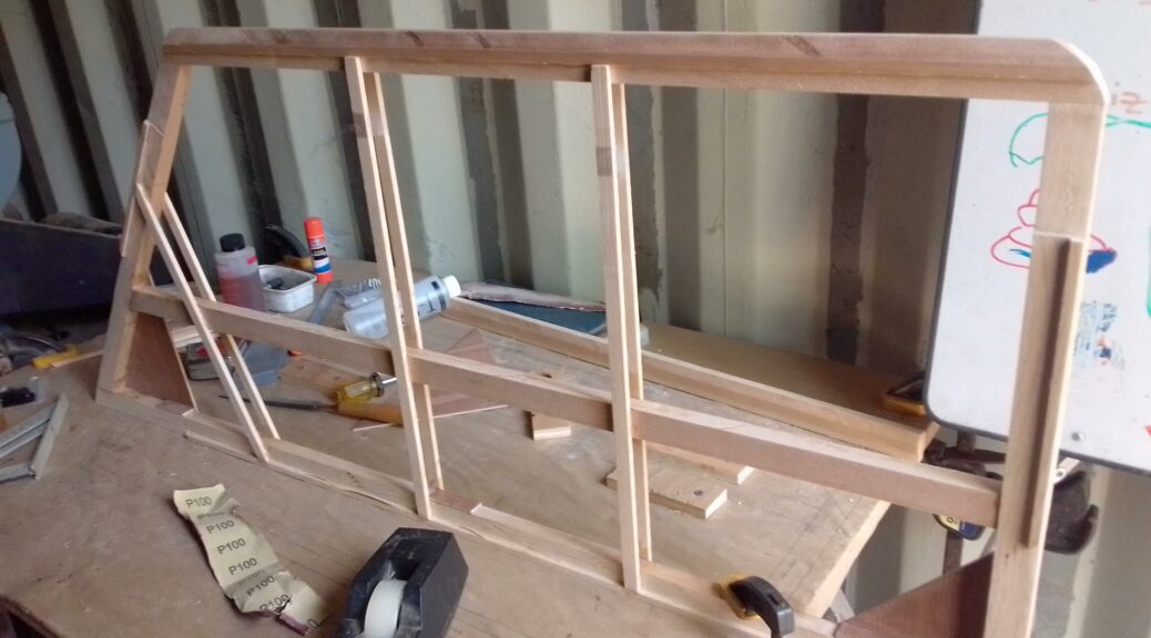
To construct a single elevator piece (two are required), twenty two spruce parts must be cut, milled, and glued together. That’s 44 custom wood parts for the elevators. And then sanding. Lots of sanding…. No wonder it takes some people ten plus years to finish one of these babies.
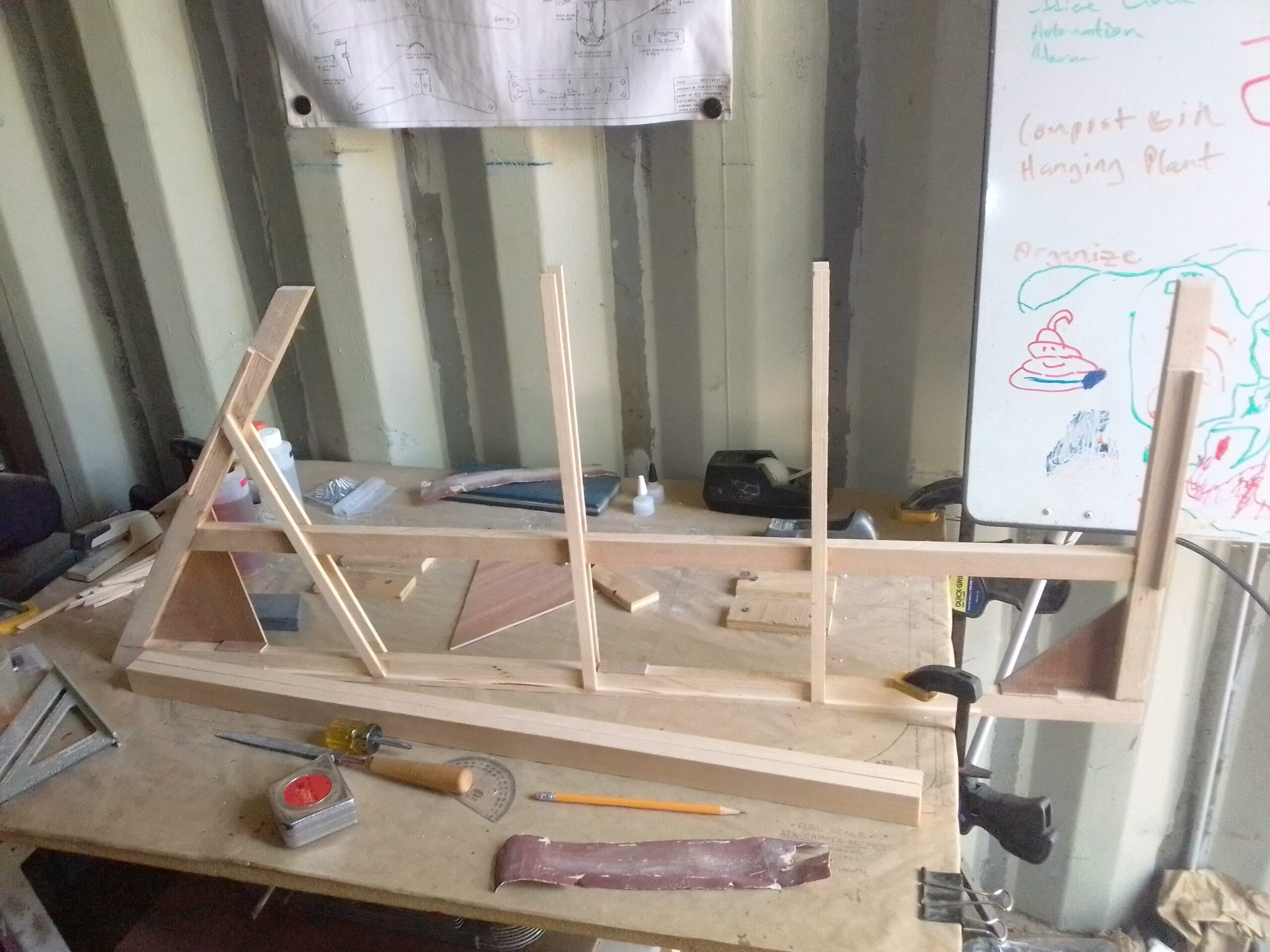
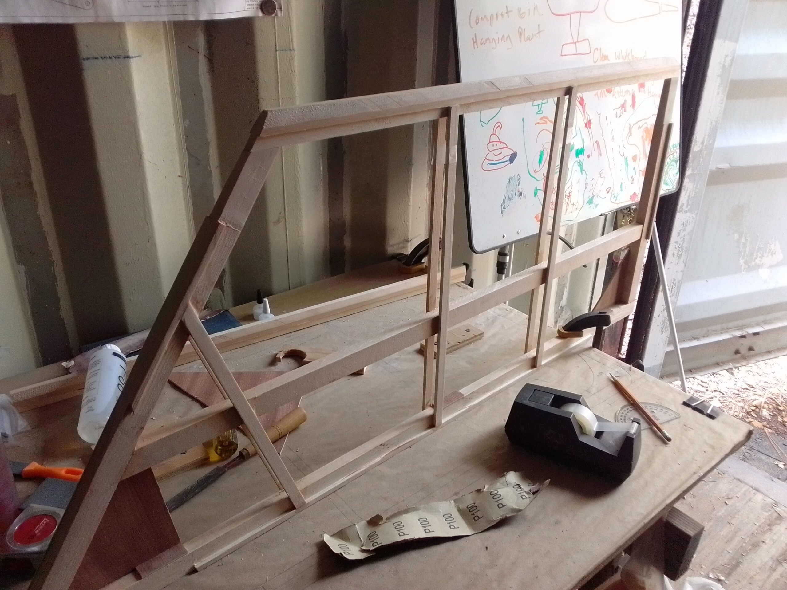
It’s finally starting to look like an aircraft part! I used gravity to hold the joints together as T-88 likes minimal clamping pressure. I used tape for clamping pressure around the spars to hold them against the trailing edge.
I have also glued on the 1/8″ backing plates for the hinges.
You may have noticed that there are only gussets on one side of the leading edge. If you are building your own Piet, it is crucial that the hinges are installed before putting the gussets on the other side. Otherwise you will not be able to properly torque the hinge bolts.
After a long break I am back to work on the Air Camper. First elevator piece is being assembled. I used T-88 Epoxy and held everything in place with a jig. Now I am waiting for hinge bolts from Aircraft Spruce. Looks like I will need to fully install the hinges before putting the gussets on the other side.
If you look closely at the next pic you can see that the hinge nuts and plate will be between the gussets and nearly inaccessible. Next step will be to get the plywood hinge back-plates built and glued in. Hopefully I will have enough time to get the other elevator piece finished before the bolts get here. Building the second identical elevator piece should go much quicker now that I have all the jigs built and the technique down.As you can see the joints are held together via the jig so there is no excessive clamping force starving the joints of adhesive.Please check back often as I will post updates as I build. If you would like to support my build you can subscribe to my YouTube channel, click on some ads or support me on Patreon. Thanks!
A CW (Morse Code) Straight Key is one of the simplest HAM Radio goodies to build. The concept is simple, short out the two Key leads. This leaves plenty of room for creativity and style with this make.
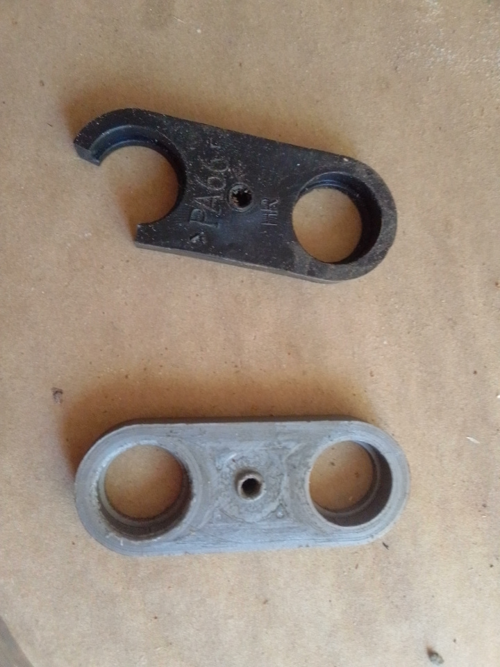
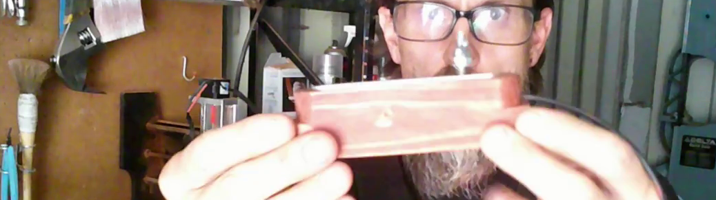
I used a piece salvaged aluminum around the size of 3mm X 13mm, a scrap piece of 2×2, some screws, washers, a spring, some ring connectors, a fulcrum pin, and a 3.5mm mono plug. I had all these parts in various “junk bins”.
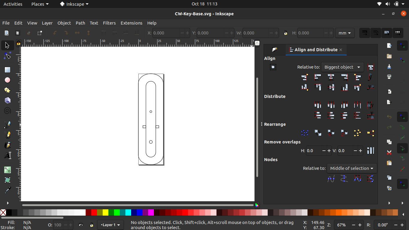
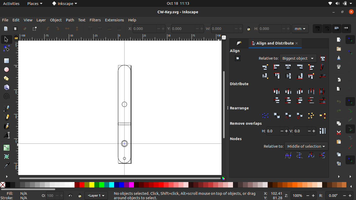
First thing I did was use Inkscape to make a simple SVG shape for carving out the wooden base from the 2×2.
I used OpenBuilds CAM (OBCAM) to create the GCODE and OpenBuilds Control (OBC) to send the GCODE to the CNC.
Next I used the surfacing feature of OBC to make a little jig to hold my aluminum piece. Then I milled the Aluminum to match the base.
With the parts all made it was just a matter of assembling and then adjusting everything to work smoothly. Add some stain and sealer and I am ready for field day!
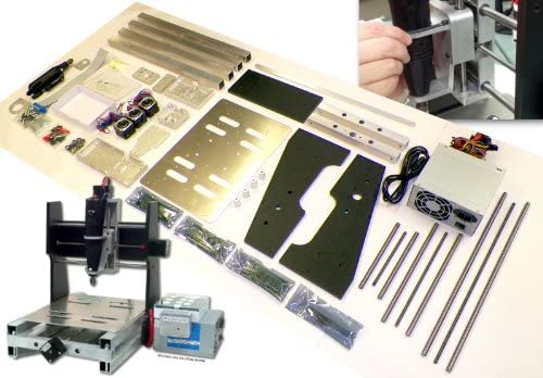
It was easy enough to assemble and get working with Linux using their FabCAM software. Well, so it seemed at first…
When the z-carriage would retract, it would skip some steps once in a while and eventually drive the tool head into whatever I was trying to mill. While the company’s customer support was responsive I could never figure the issue out and the project got shelved.
Long story short the company is no longer around but the machine was. Sitting on my shelf, sadly doing nothing.
Then one day while shopping for 3D Printer upgrades, I ran across this Arduino kit on amazon that will replace the proprietary brains, motor controllers, and software with a well supported open source system, GRBL.
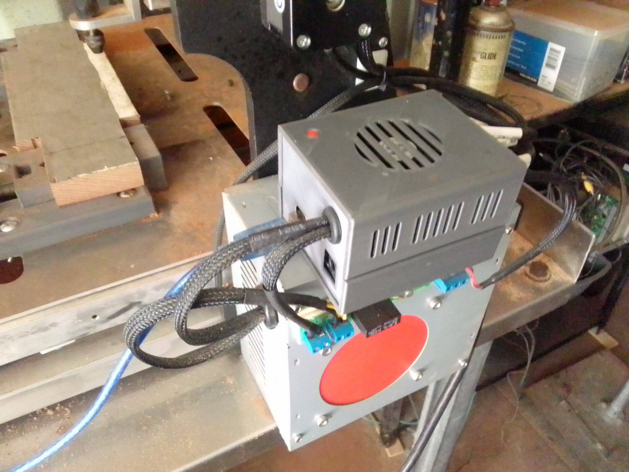
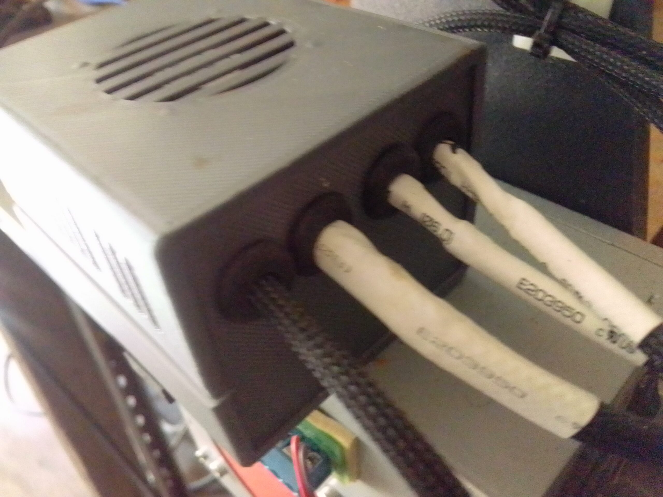
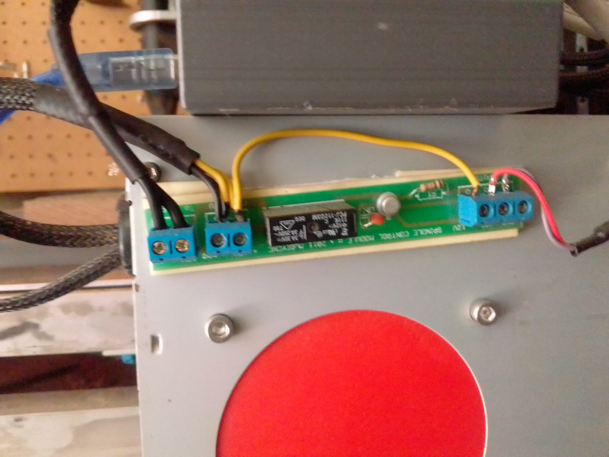
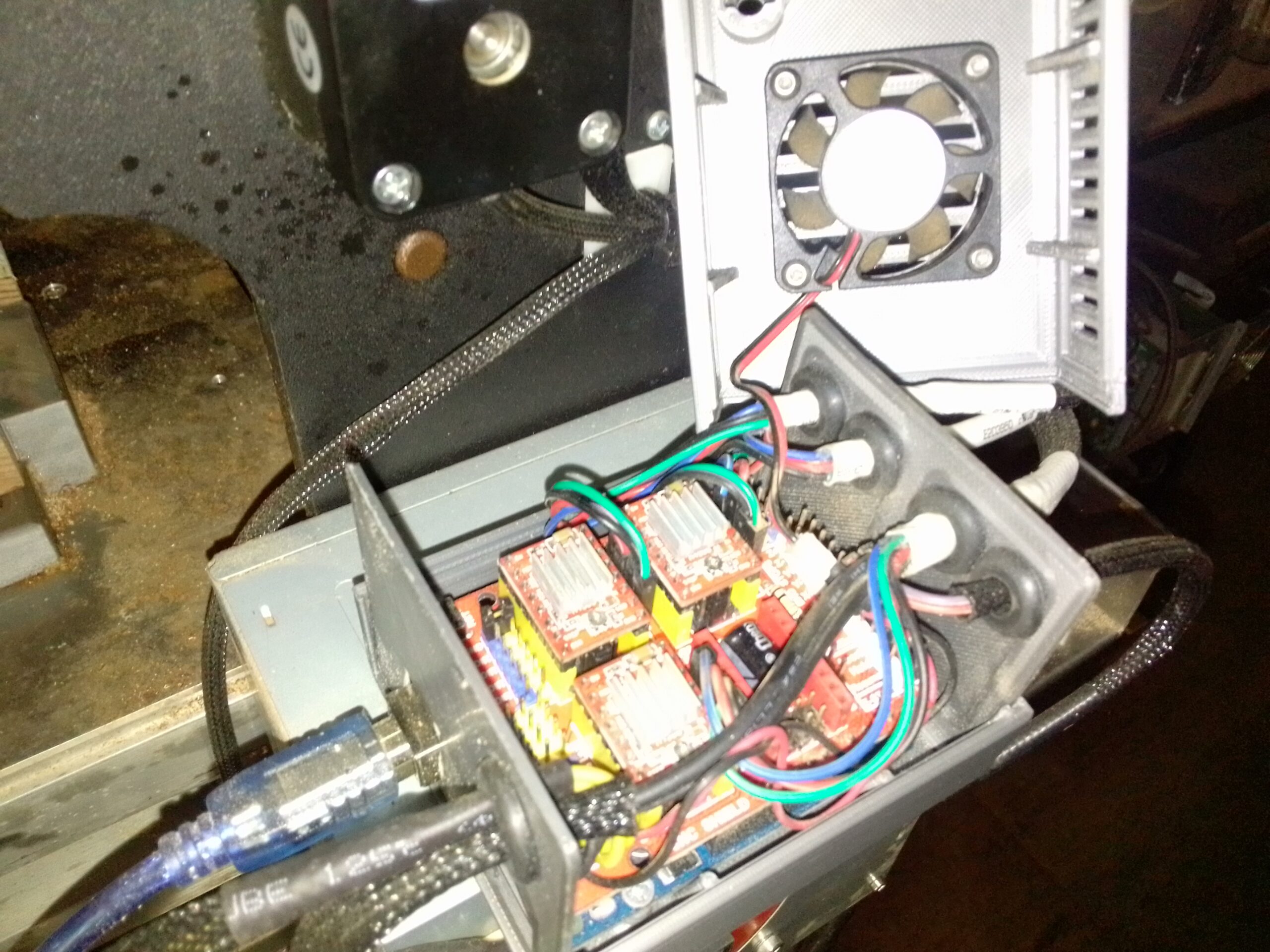
I used the power supply that came with the MyDiyCNC kit as well as the original spindle relay. The two wires on the right go to the spindle pins on the Stepper Hat:
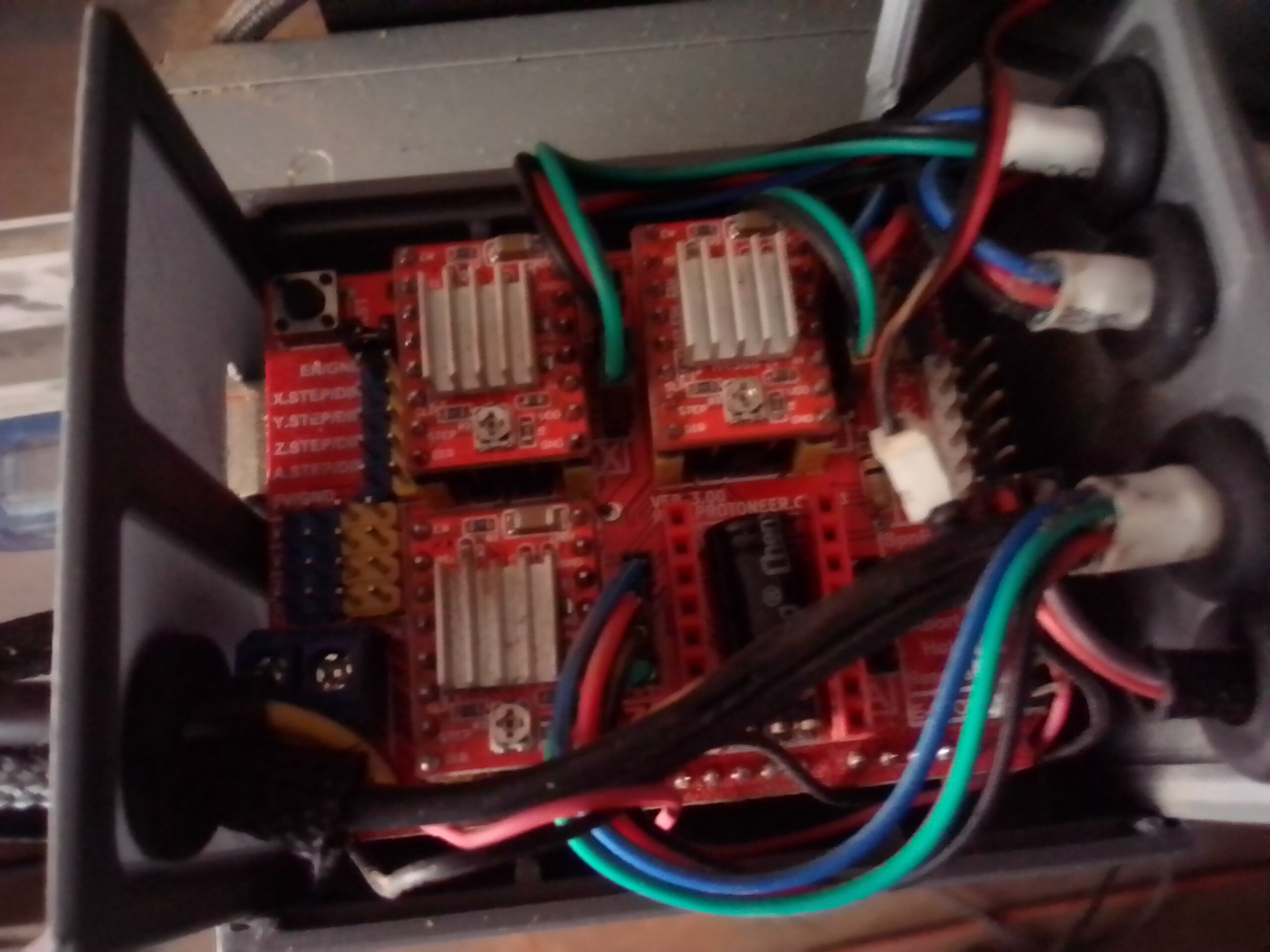
I soldered some female plugs from jumper wires onto my motor wires and attached them to the motor driver output. Color order from top (reset button side of board, see photo) is Blue, Red, Black, Green:
I hooked the 12V+/- output from the power supply to (yellow+, black-) to the controller hat. This is also where I pulled 12V for the 40mm enclosure fan.
Don’t forget to put a jumper on the enable pins (right of reset button).
Once everything was all hooked up I adjusted the motor controllers amperage to 400mA (for the stock motors that came with the kit, your mileage may vary) using this guide.
Now you just need to flash GRBL to your Arduino and get some software for your computer. Here are some helpful links and files that go me through the rest of the setup phase including jumper settings for microstepping:
The last tweaks to get it to work correctly was to set the X, Y, Z max speed to 350mm/min (Firmware Settings) and 1/4 micro-stepping (Jumper under motor driver).
I have been using OpenBuilds Control and their integrated CAM software. It works fairly well, though the GUI is prone to crashing. Upside is that when the GUI does crash, the job still completes. Unfortunately he crashed GUI can make it difficult to find perfect zero again.
Universal Gcode Sender will definitely play with GRBL and control the machine. However I have yet to use it to actually run a job. I will post updates after I give it a try.
Feel free to post any questions in the comments section below!
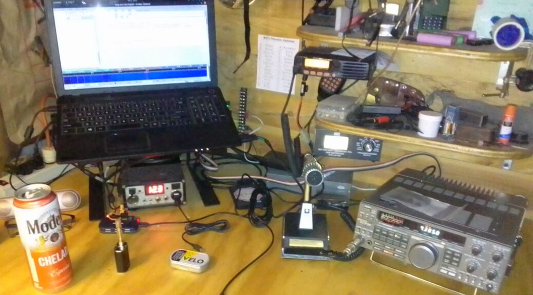
My radio club, SFARC, has helped me get into an HF rig, namely the Kenwood TS-440S. This radio is a bit old (1986ish) but, IMHO, this thing is awesome. It has a fairly compact form factor, runs of my 12V off grid power without issue, and with the following upgrades will talk to my computer.
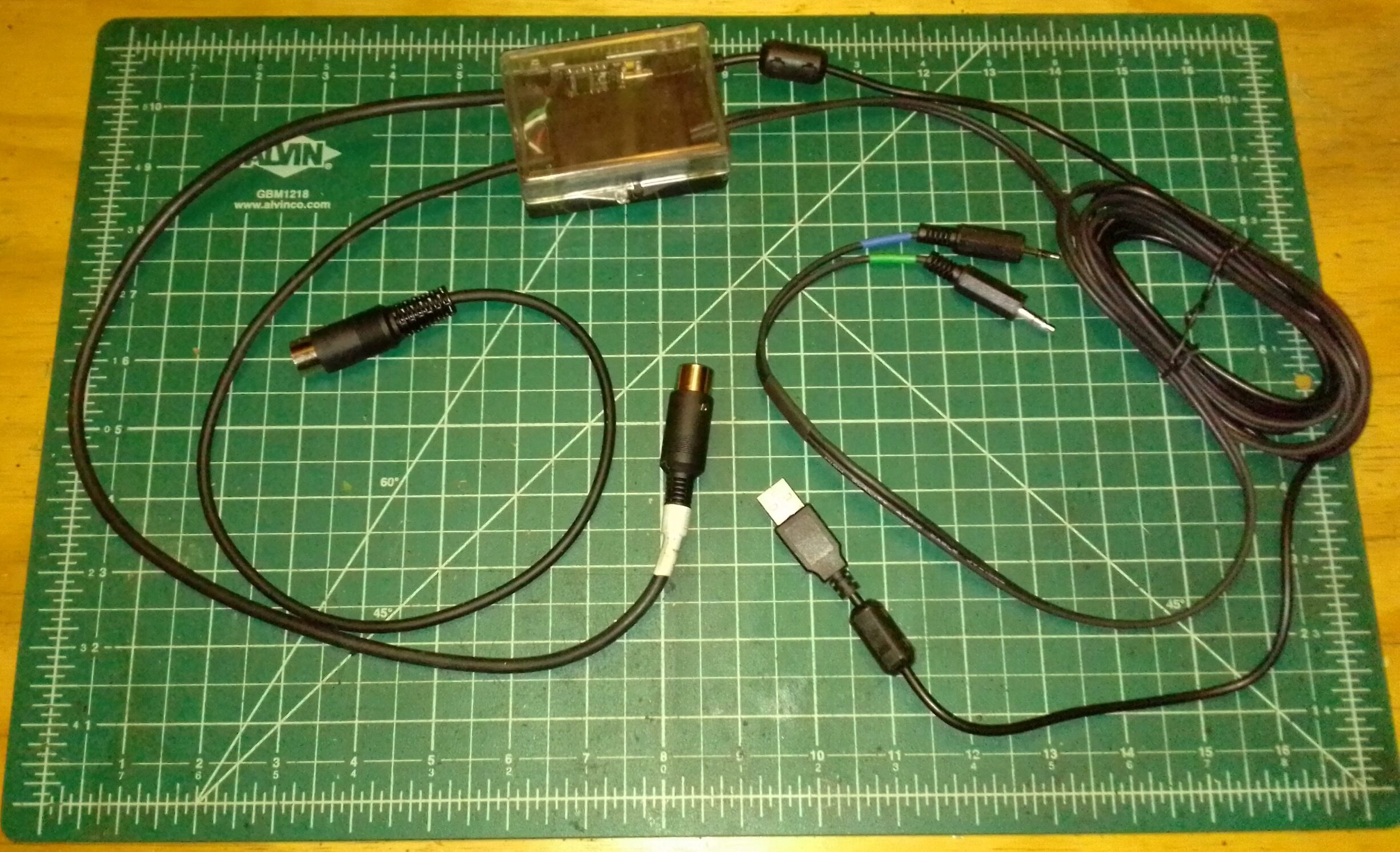
I first purchased a digimode cable that has opto-isolated audio input/output as well as a USB PTT coupler which is allowing me to experiment with digital modes on this transceiver. While this is great, I would like to be able to view and control the frequency of my radio from FLDIGI via HamCAT or hamlib. Turns out this will require a little bit of hacking (awesome!) to get it working.
Kenwood TS-440 Digital Interface Cable
Issue #1: The 13 pin DIN, ACC 2, only provides audio and PTT functions. If I want to provide a serial interface I need to use the 6pin DIN, ACC 1, interface. I need to build an interface cable.
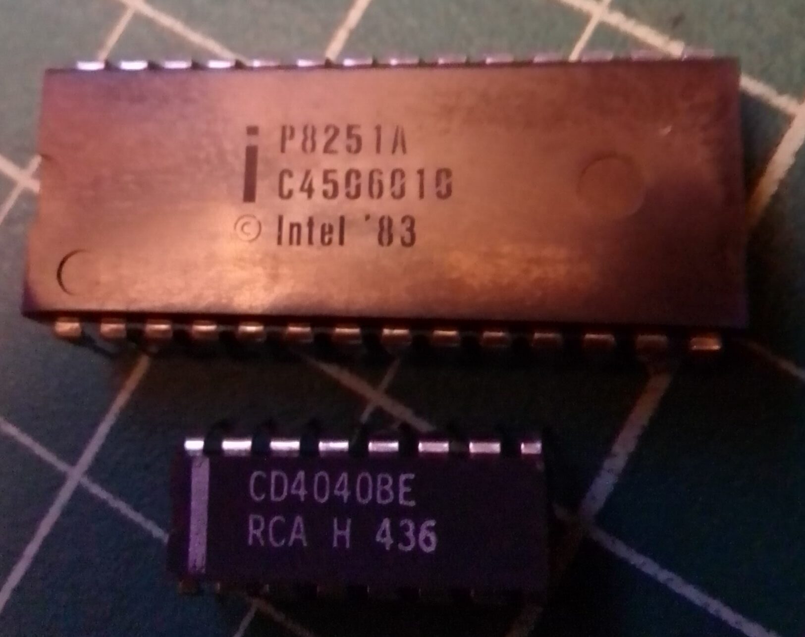
Issue #2: This interface is a serial connection using TTL voltage (5.5v) but with the same logic as a standard serial port. I need an FTDI breakout board with inverted logic.
Issue #3: The 440 requires an upgrade kit (IC-10) to provide serial communication capabilities. This kit is semi-rare and costs about 50 bucks.
In this article issue #1 will be addressed with a six pin din plug ordered from amazon.
Issue #2 will be handled by an FTDI USB board I already have on hand and an XP virtual machine running FD_PROG to invert the logic. Unfortunately this makes this solution NOT 100% Linux. To resolve this I will use the command line Linux program ftdi_eeprom to clone my firmware and post it here so Linux only users can use ftdi_eeprom or flashrom to program their FTDI boards with ease.
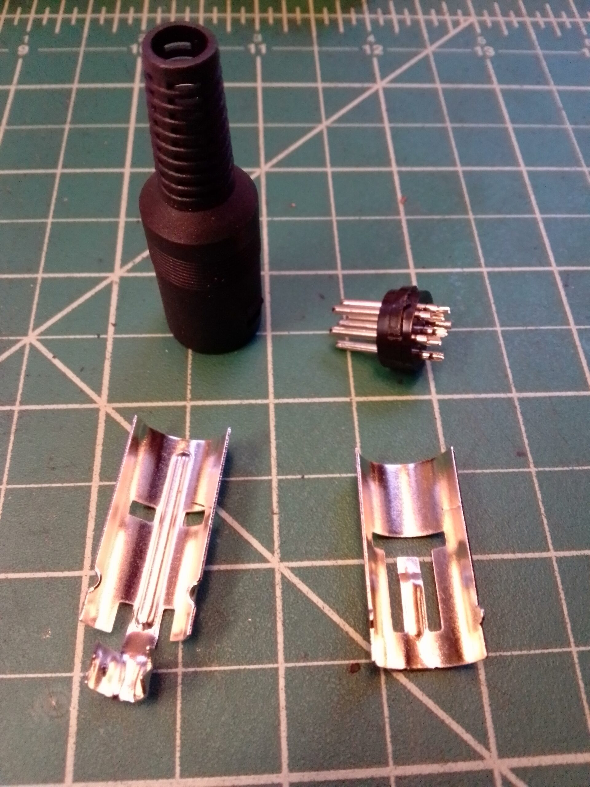
After receiving the plug from Amazon, I repurposed a shielded USB cable to build the plug. I hooked up all the wires even though CTS/RTS were not required. RFU style as it were. Perhaps adding flow control in the future would speed things up. I don’t know I haven’t tried. Anyway….
Disassembled Plug
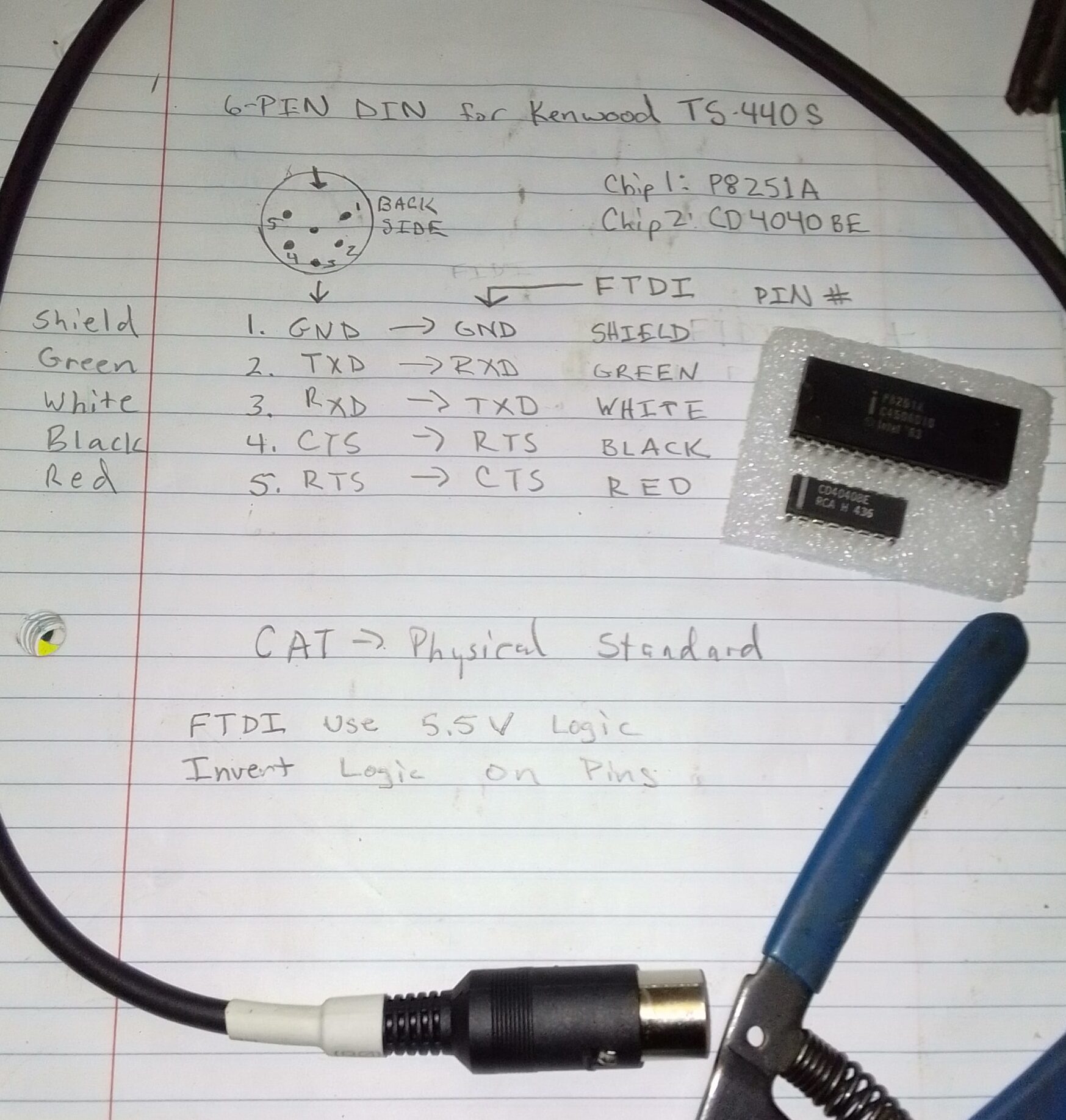
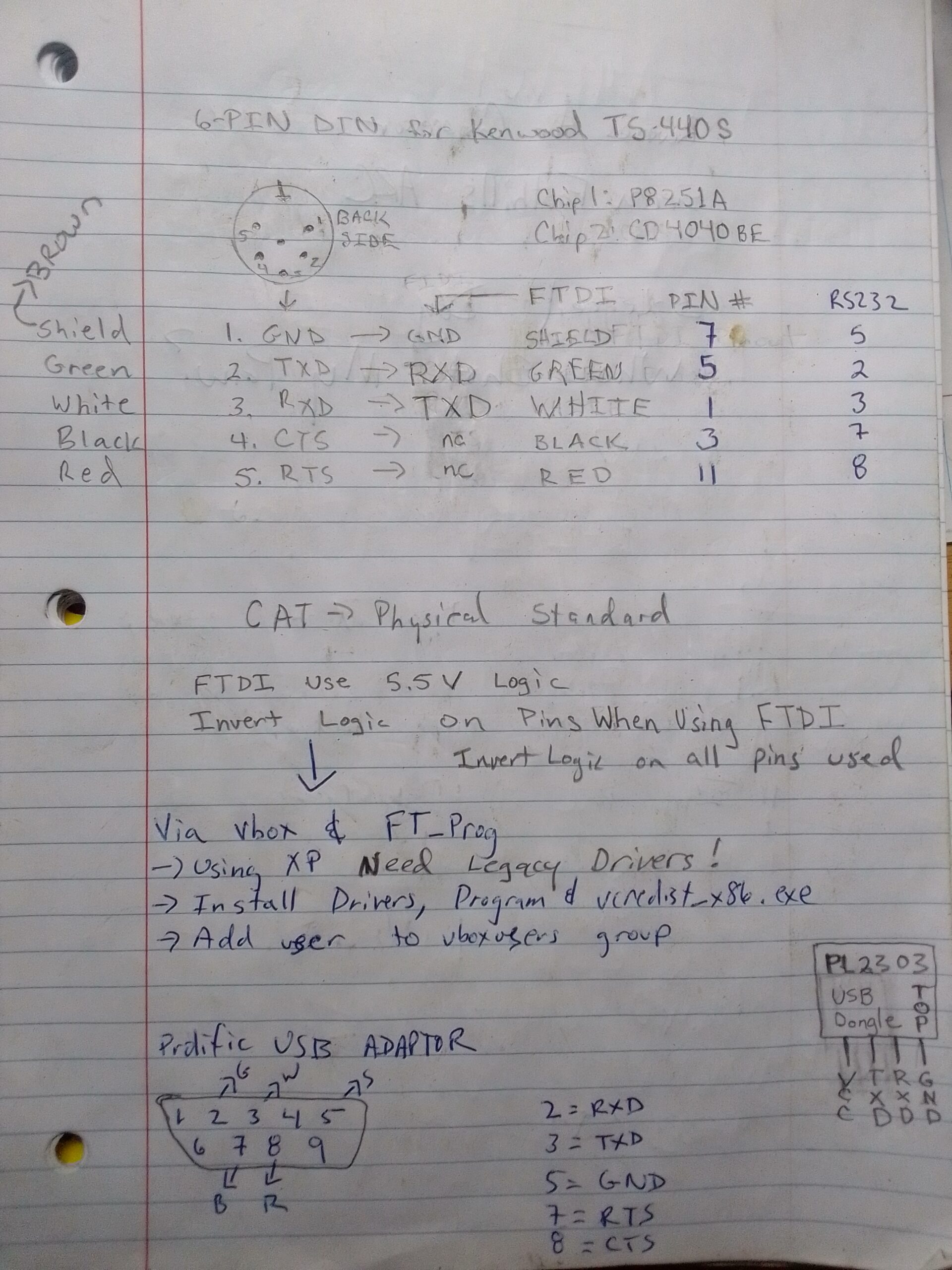
These are the pin numbers as viewed from the solder side:
GND
TXD
RXD
CTS
RTS
Here is how I hooked up the 5 wire USB cable:
GND -> Cable shield
TXD -> Green
RXD -> White
CTS -> Black
RTS -> Red
Wiring Diagram
#2: Install the chips.
After I received my chips, I installed them following this guide. To sum up, remove the top and bottom cover from the radio. Then remove the face-plate screws and then loosen the 5 small screws for the metal grounding plate so it may be removed. Once this is done the chip slots will be exposed ( they are the only two empty slots on the back of the face-plate ). You will need to use a flat surface to bend the pins slightly inwards so that they will line up with the sockets when you insert them. Pay close attention and make sure the chips are fully seated properly into the sockets.
Once this is done reassemble the radio and ensure that it is working properly. Now the ACC 1 port has serial com capabilities.NICE!
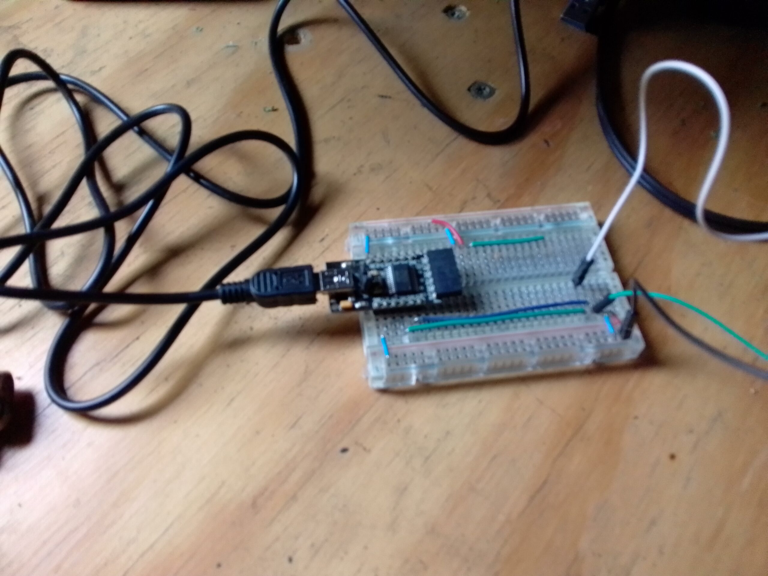
#3: Hook Up the FTDI Breakout Board
The only pins required for communication are GND, TRX, and RTX. You supposedly can use a 5 wire connection using CTS/RTS flow control but it is not necessary. The FTDI breakout I used for this project only made CTS and DTS readily available so I went with the three wire setup. There may be advantages to having flow control and I would be interested to hear input on this in the comments.
My Notes
Attach the TX from your rig to the RX on the FTDI and the RX from the rig to the TX on the FTDI. GND goes to GND.
FTDI on the proto board
#4: Program the FTDI Board
Although the wiring is done, we still need to invert the logic on the FTDI board. There is no linux app to easily do this so I ran the FD_PROG utility using an XP virtualbox install to run this program. There are multiple drivers available from FTDIChip, make sure you use the correct driver for your system.
If you don’t have a windows install to program your FTDI chip, you can flash the following firmware to your FTDI chip using ftdi_eeprom. This firmware has the inverted logic necessary to communicate with your rig.
Download both files to the same location, plug in the FTDI and program it. Something like this:
ftdi_eeprom --flash-eeprom ftdi.config
#5: Time to play radio!
You can now use FLDIGI or similar to read/send the frequency and PTT key your radio. Software config is beyond the scope of this article, but this is what it looks like:
If you enjoyed this article you can support me by subscribing to my YouTube channel and/or visiting some links from my sponsors. Thanks!
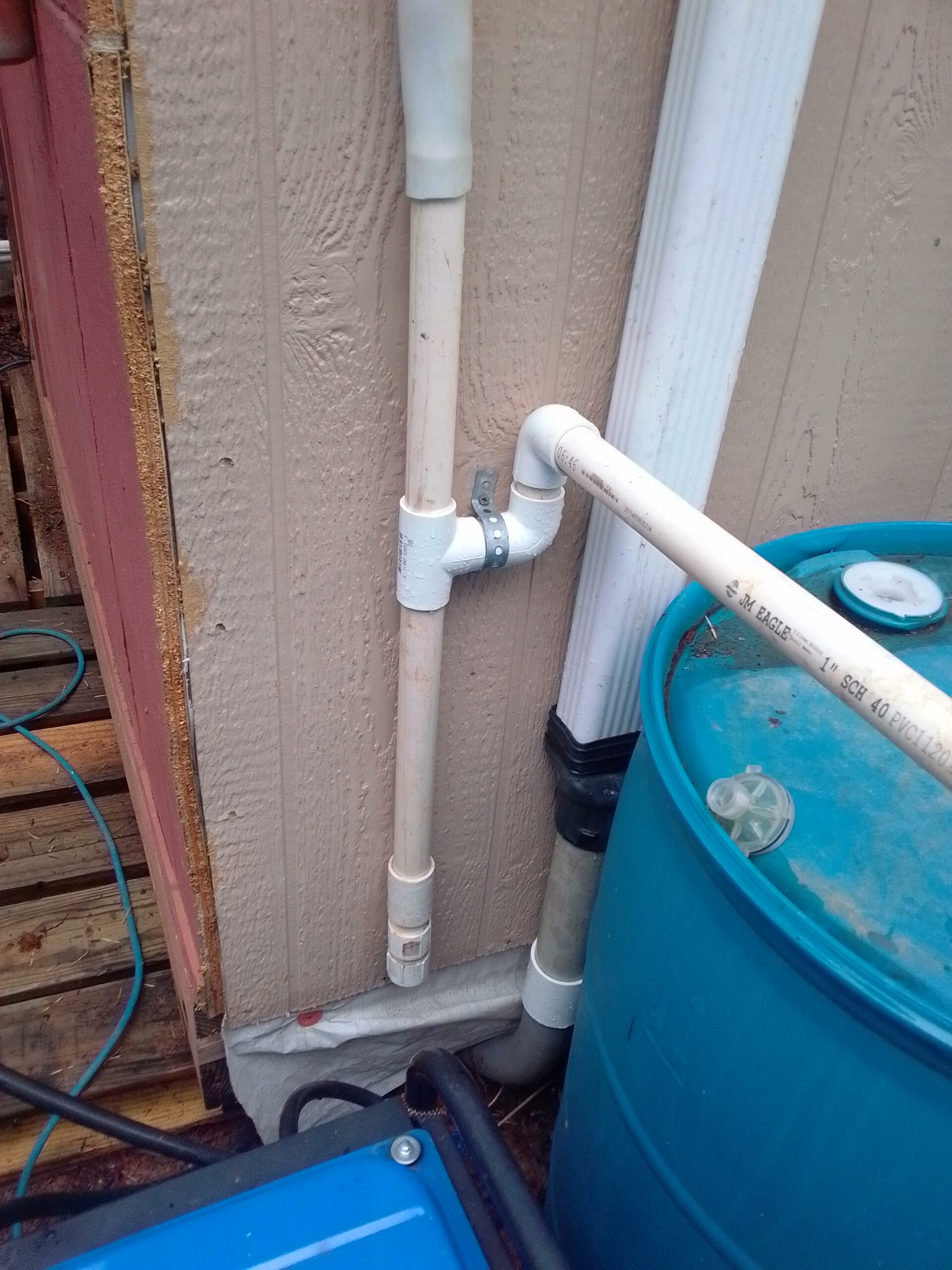
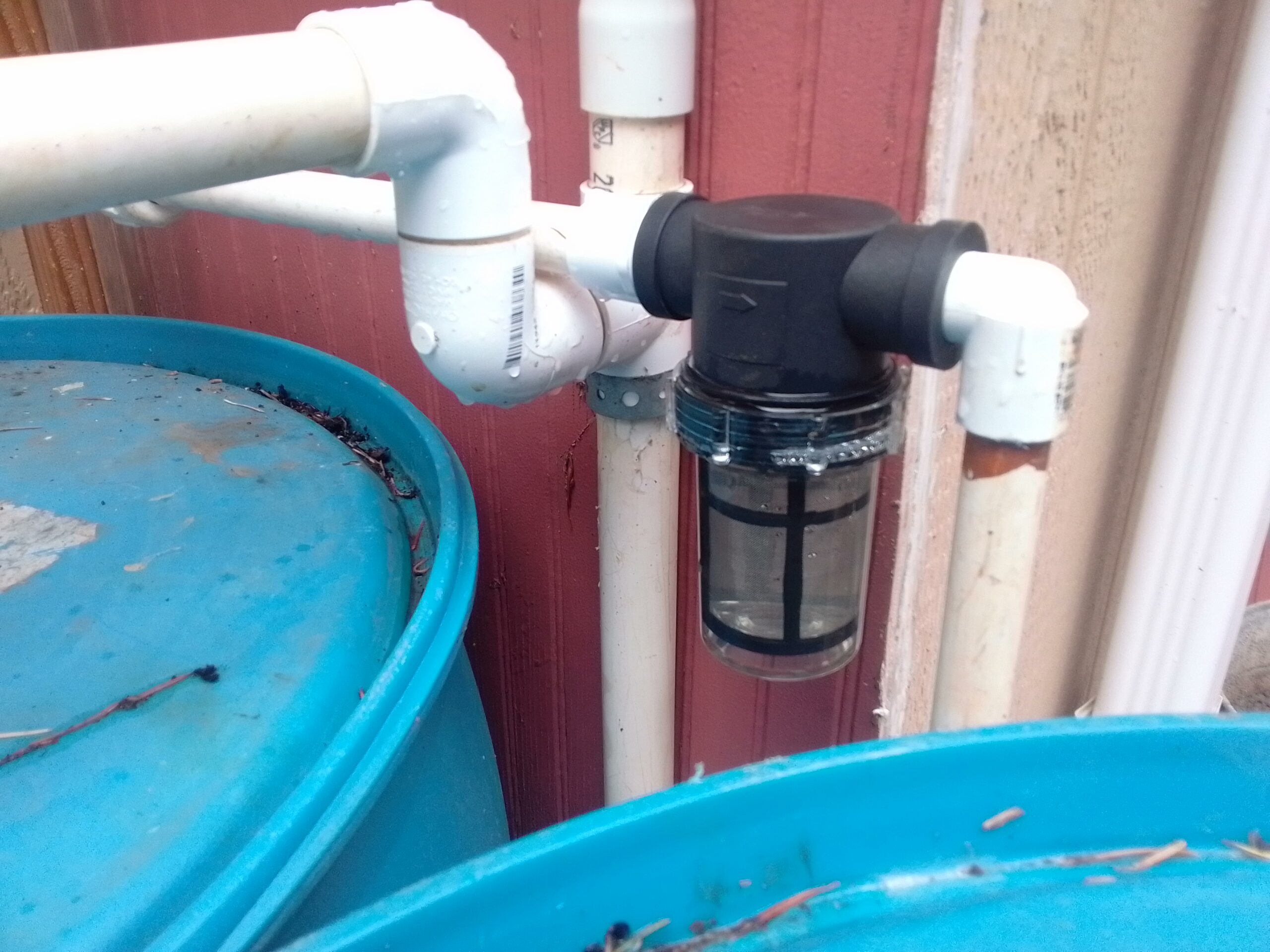
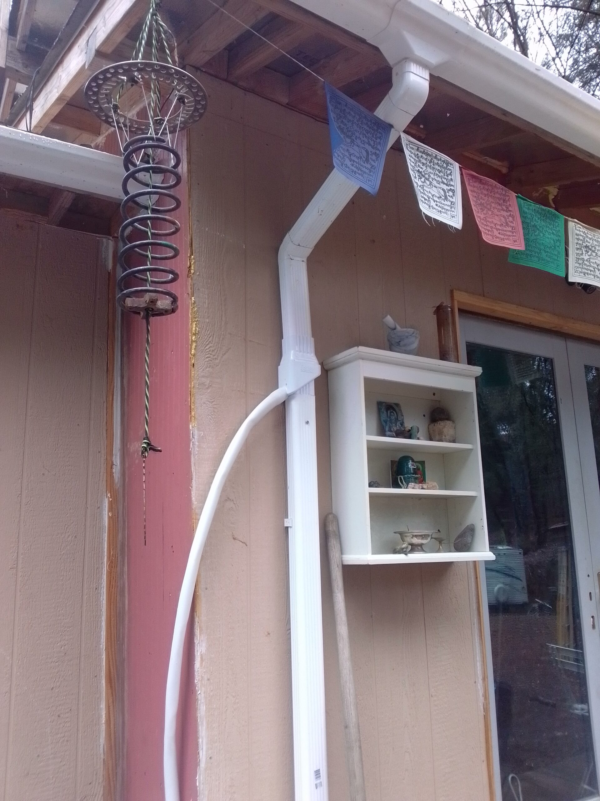
I have completed my rainwater collection system. All said and done I think I spent less than $100. The first time I did my dishes with rainwater was the first time I felt truely off grid. What an amazing feeling! Water from the sky!!!!
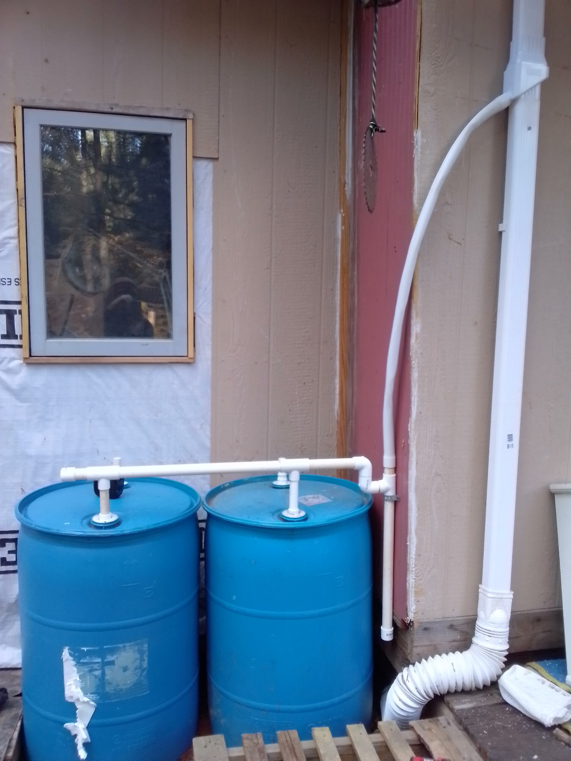
The barrells were salvaged from a construction company up the road. They originlly contained Blue Def for the company trucks. I figure this is OK as I won’t be drinking the water from this system and, of course, I rinsed the insides out as best as I could before putting them into use.
For the pump to pump the water into my house I used a water pump salvaged from an RV. If you can’t find one for free you can Buy one Here on Amazon for about $75.
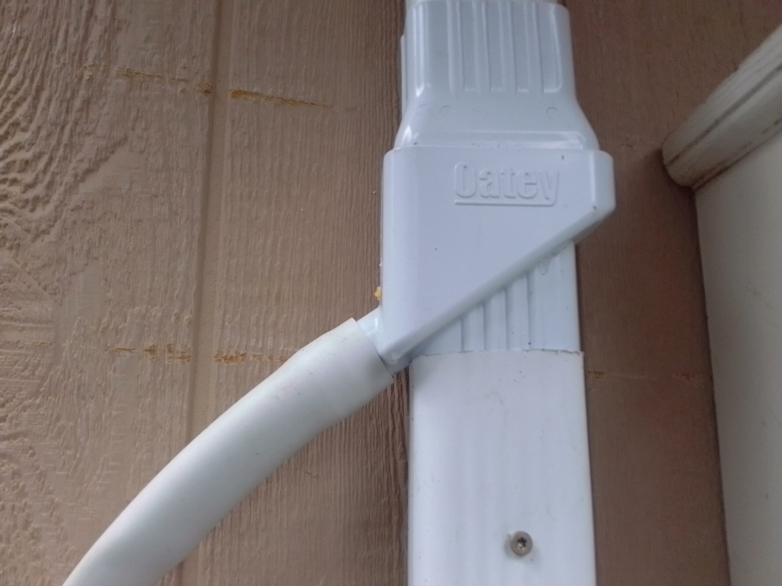
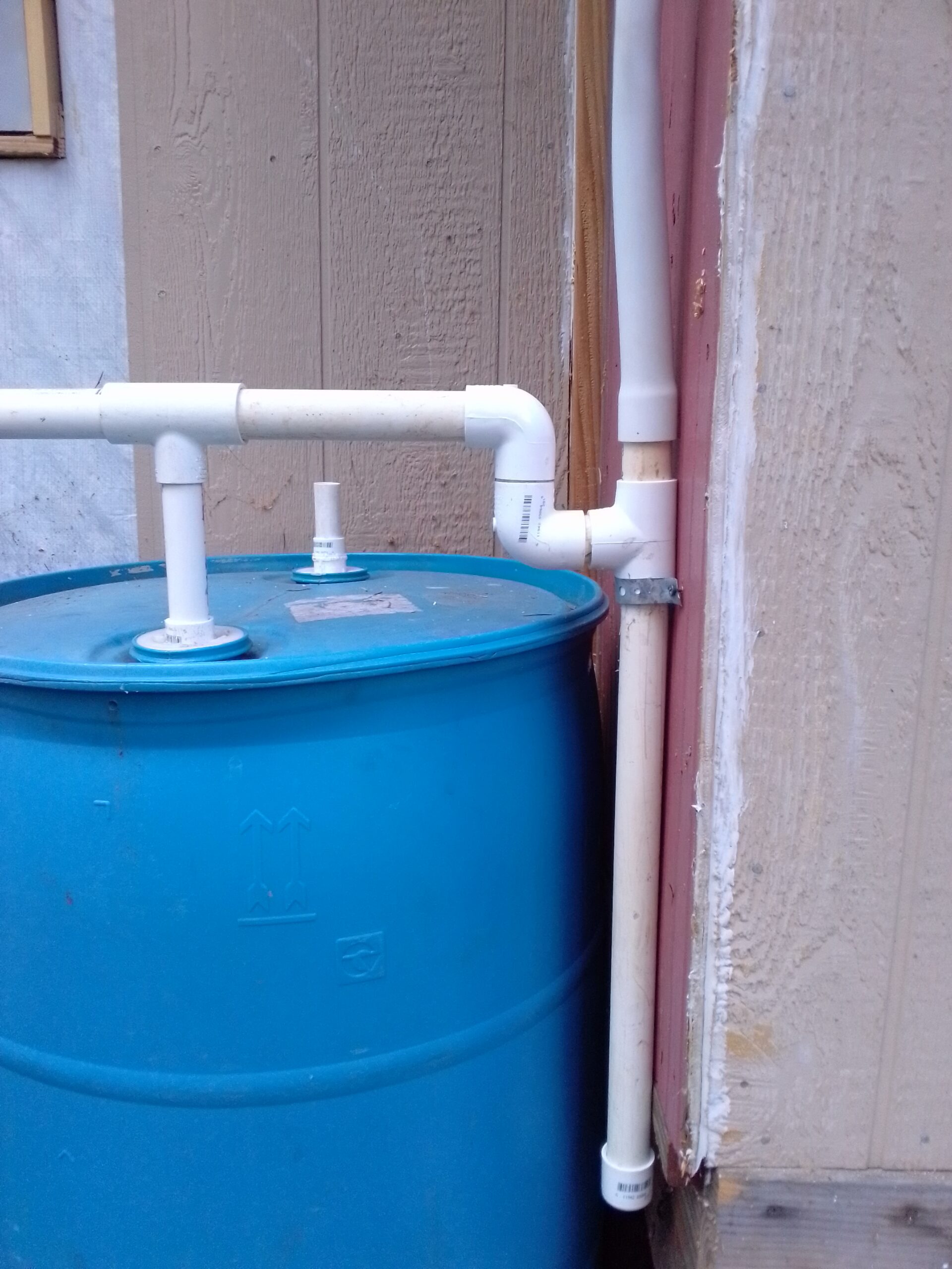
PVC P-Trap for particle / sediment collection. Cap on bottom unscrews for cleaning.Sediment Filter on Water OutputTanks installed!Oatey DownspoutBuy Oatey Rainwater Collector on AmazonP-TrapDay one of the build, only two barrels at this point.
My first spruce shipment came in last Friday! I decided to build some of the smaller parts first so I ordered the vertical stabilizer kit and the elevator kit. I already have the space to build these parts and I figured it would be an easy place to start. I was slightly mistaken about the easy. This “mistake” is actually working in my favor. It has given me time to perfect my mental build of the craft, see how the build process will be best accomplished, and is getting me mentally prepared for the meticulous nature of this undertaking.
Layout of elevator parts before milling.
The plans and instructions on building the empennage aren’t entirely clear and must be studied thoroughly. Much googling and reading of forums revealed that I was not the only one that found these pages of the plans “left to interpretation”.
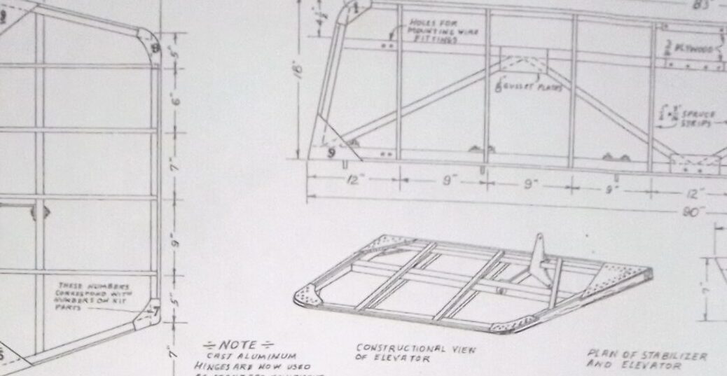
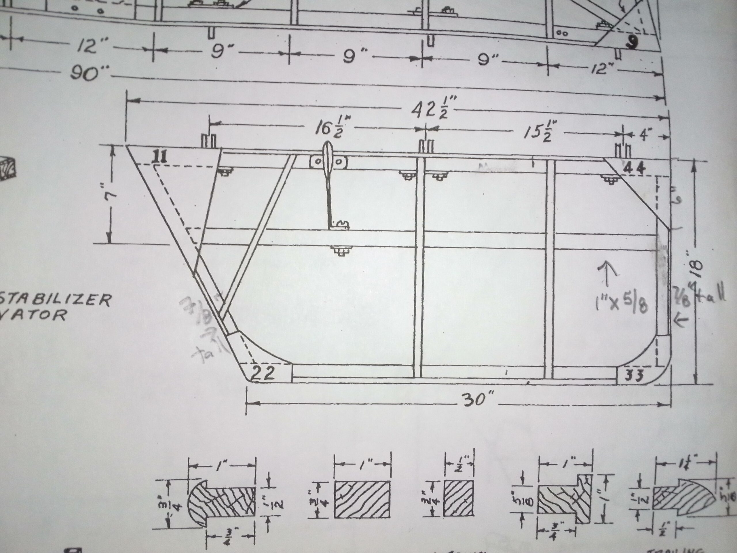
Elevator as pictured on the plans.
There are no definitive dimensions for the gussets. They are numbered with a note that says “These numbers correspond to parts in the kit.” The “kit” from aircraft spruce just contains a peice of 1/8 plywood for the gussets to be cut from. I could not find patterns or dimensions anywhere. Also the dimensions for the center beam seem to be only for the stabilizer and the correct dimensions for the center beam on the elevator must be deduced. The solution ended up being quite simple, I made a full scale drawing of the elevator. Once this was done, figuring out dimensions and designing the gussets was actually quite simple.
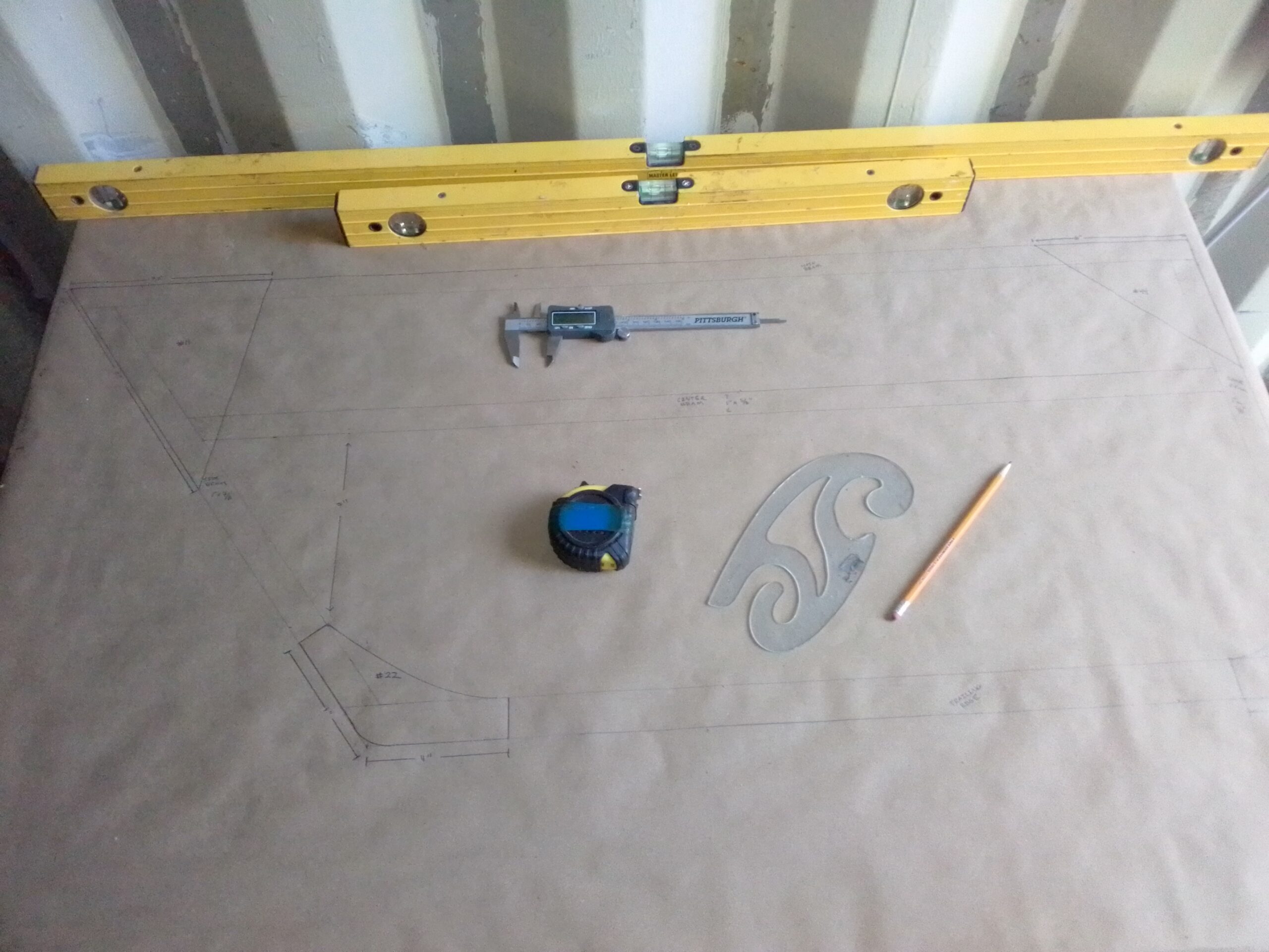
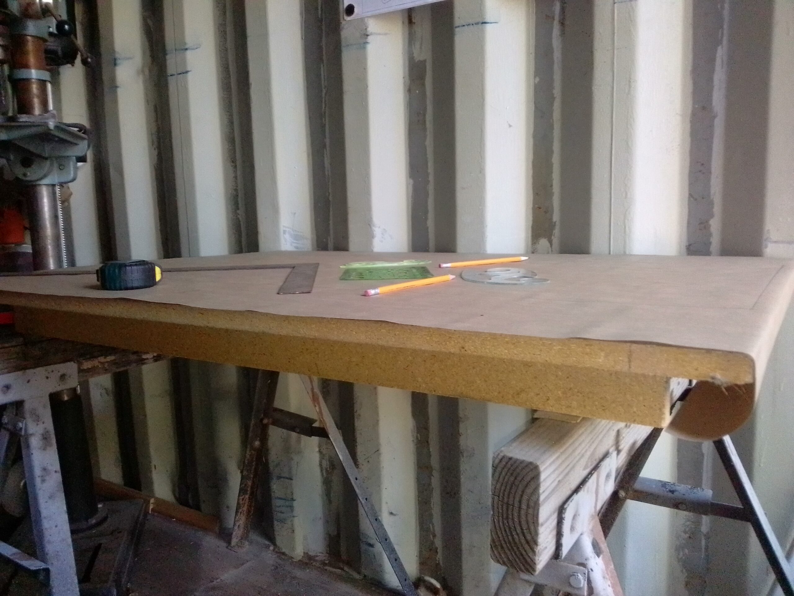
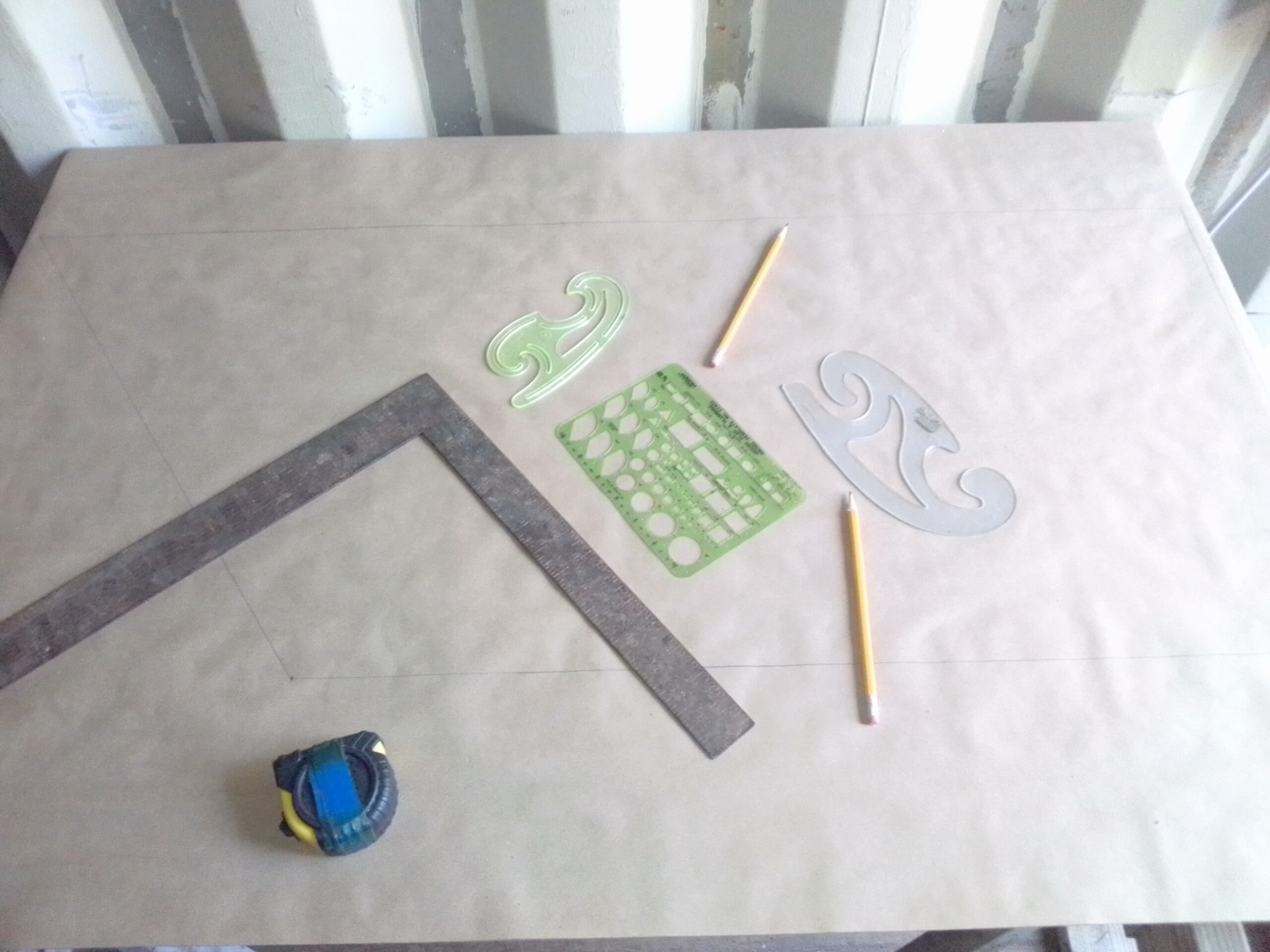
Caliper, straight edge, rulers and swoop stencil
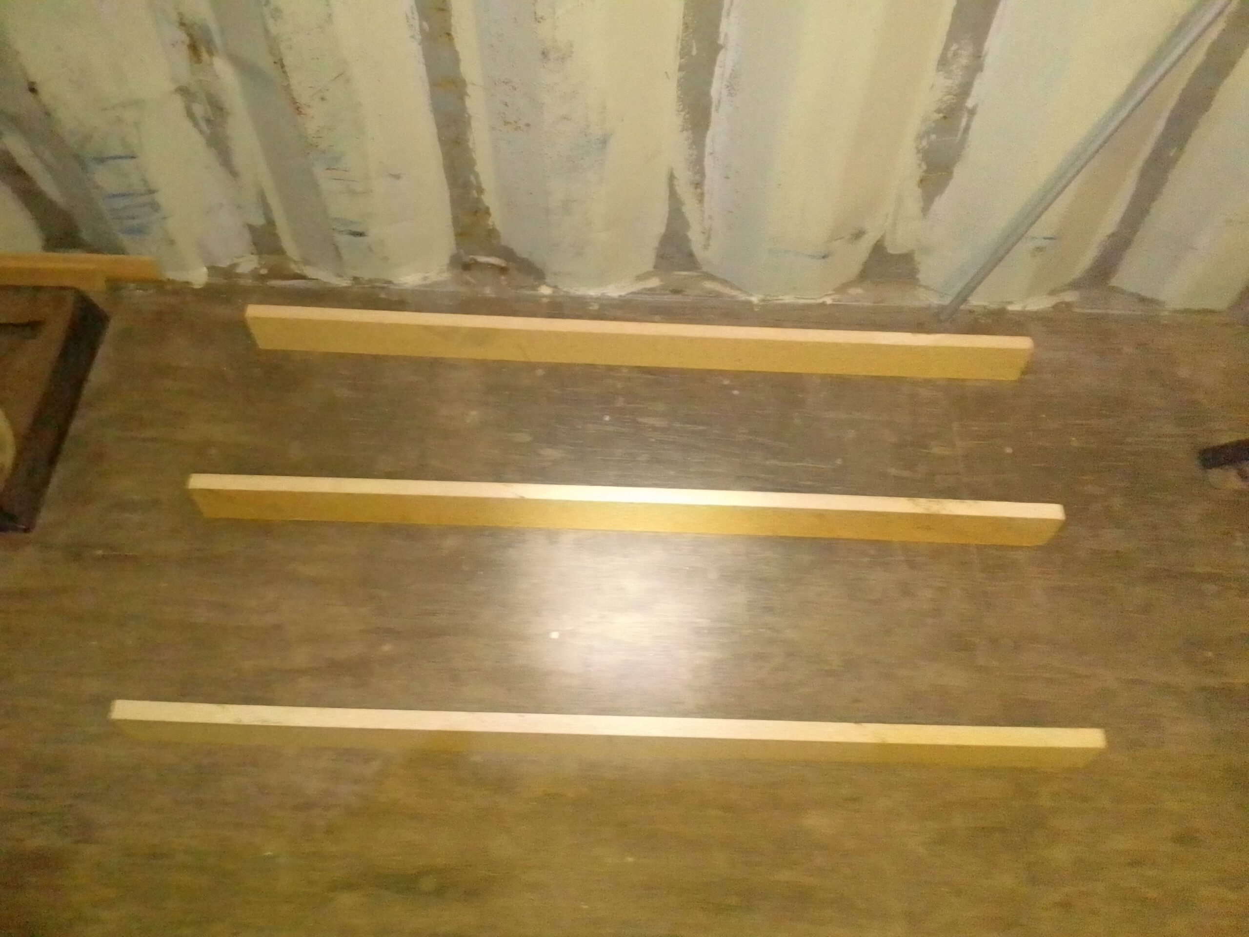
I began by constructing a simple build surface that I could screw wood to to form a jig for the elevator. I used some scrap particle board and made some 2.5″ spars with my table saw. I spaced these out on the floor, put a bunch of wood glue on the upward facing surface and then set my build surface (3/4″ particle board) on that. I weighed down the top with heavy things and let it dry overnight.
Spars for underside of build surfacesurface glued to spars weighted down overnight
The next morning I screwed the “table” to my sawhorses with two 6″ screws. I put one screw down from the top and through the middle spar into each sawhorse. Then I used shims under the other spars to make the surface flat in all directions.
build surface attached to sawhorses and shimmed to perfect flatness
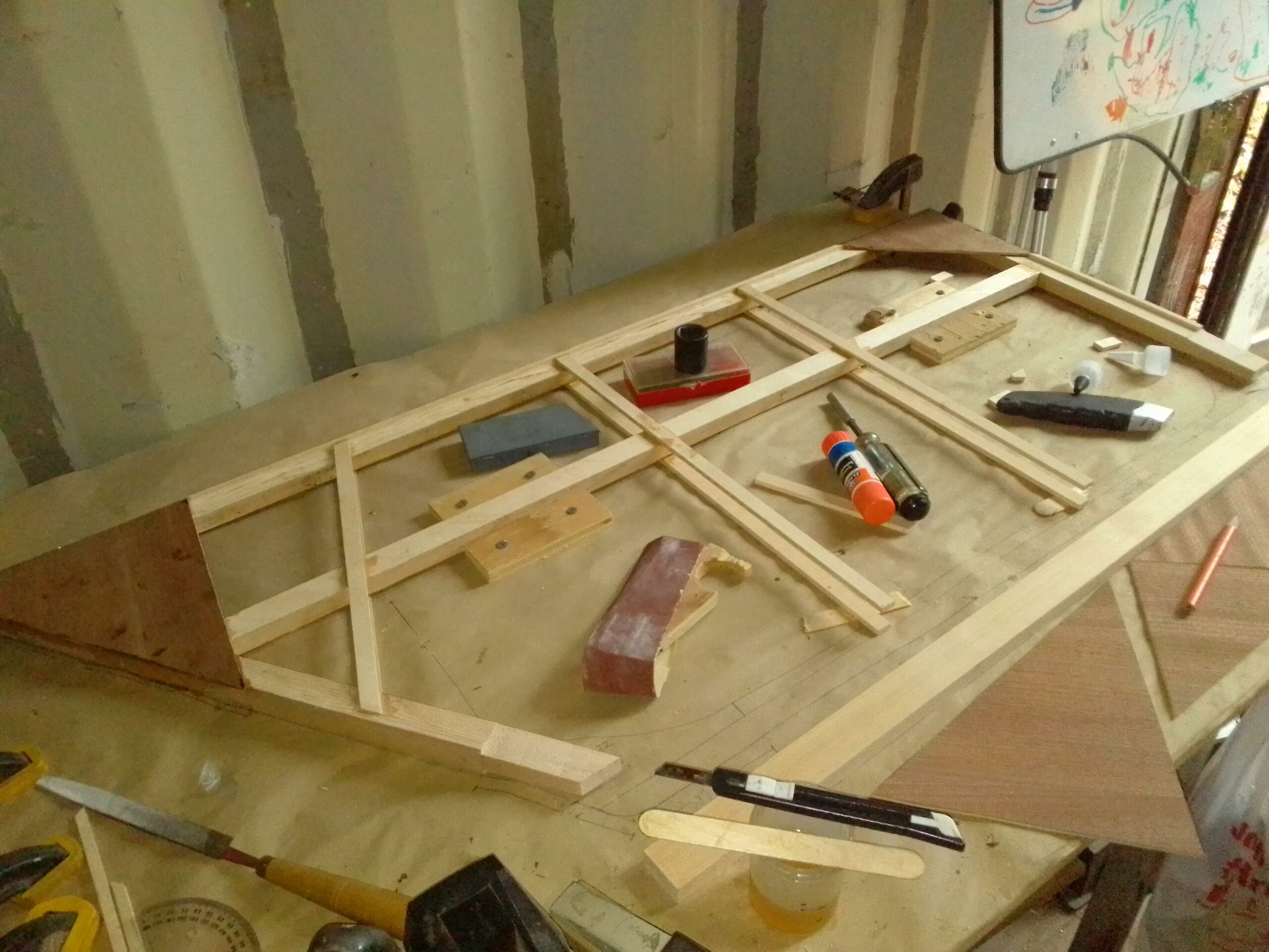
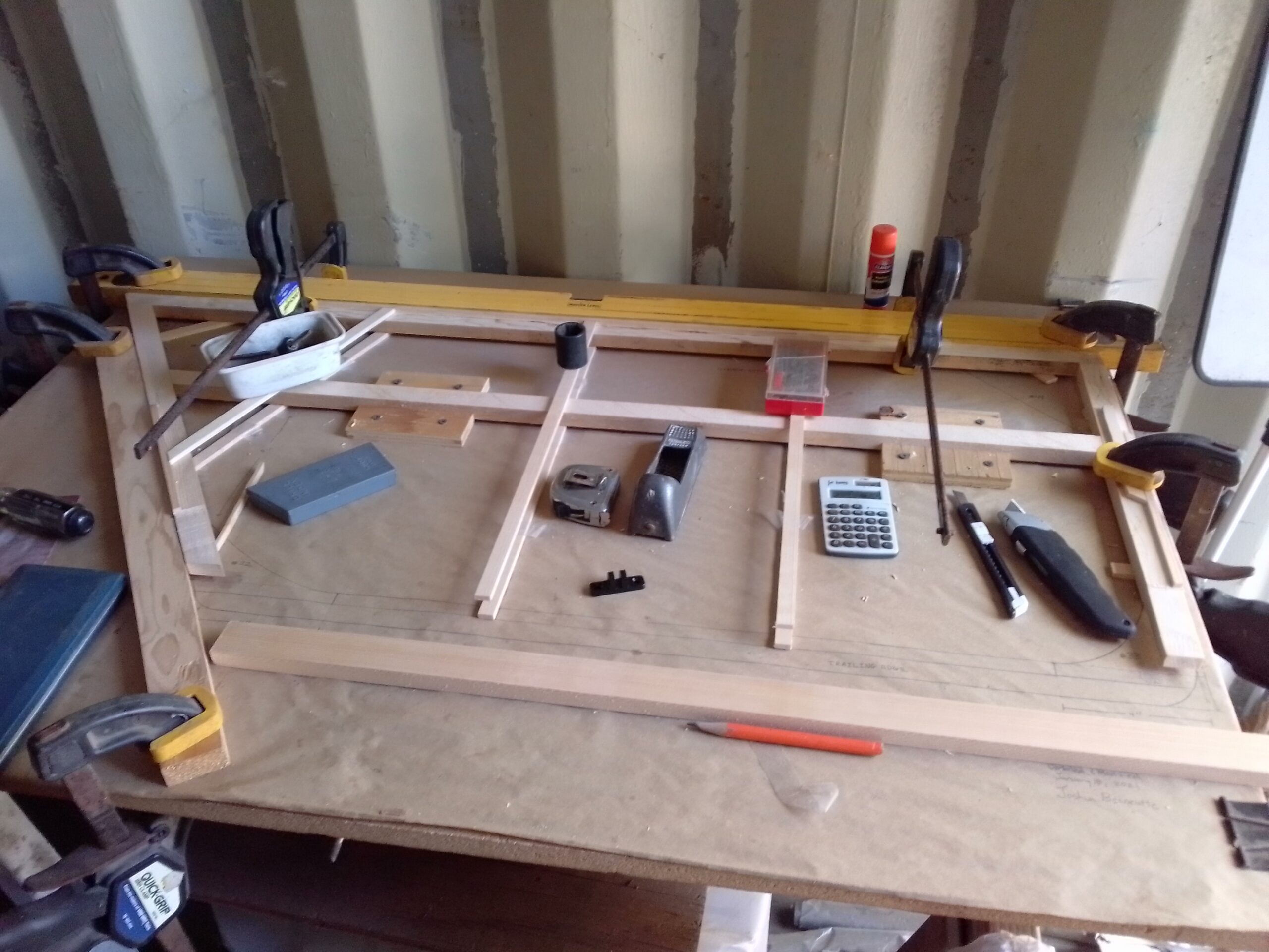
Once my surface was ready, I covered it with kraft paper and meticulously translated the elevator blueprint to full size on my build surface. I then came up with what seemed like the correct dimensions for the gussets and used the pictured swoop stencil thingy to do the rounded corners.
Stencils, rulers, a square, and some really sharp pencils.Translating blueprint to full size.
When it comes to holding gussets in place while glue dries, if you ask 5 builders you will get 10 suggestions on the best way to do this. The original plans call for cement covered flat head nails. It has been recommended by some to use a pneumatic nail gun to staple or nail them into place. Some say pull the fasteners, some say leave them in… Some say use weights, some say light clamps. Goodness… what to do? Well, after drawing up the full size plan, I’ve decided that building with a jig and just using small weights to hold the gussets while the epoxy dries is going to be the method for me. Both elevator pieces should be identical, so building everything in a jig makes the most sense. This also will allow me to miter and assemble the entire unit without having to glue anything until it is perfect.
I will be posting a YouTube video explaining this more thoroughly. I am also intending to come up with full size patterns for the gussets which I will make available on this website.
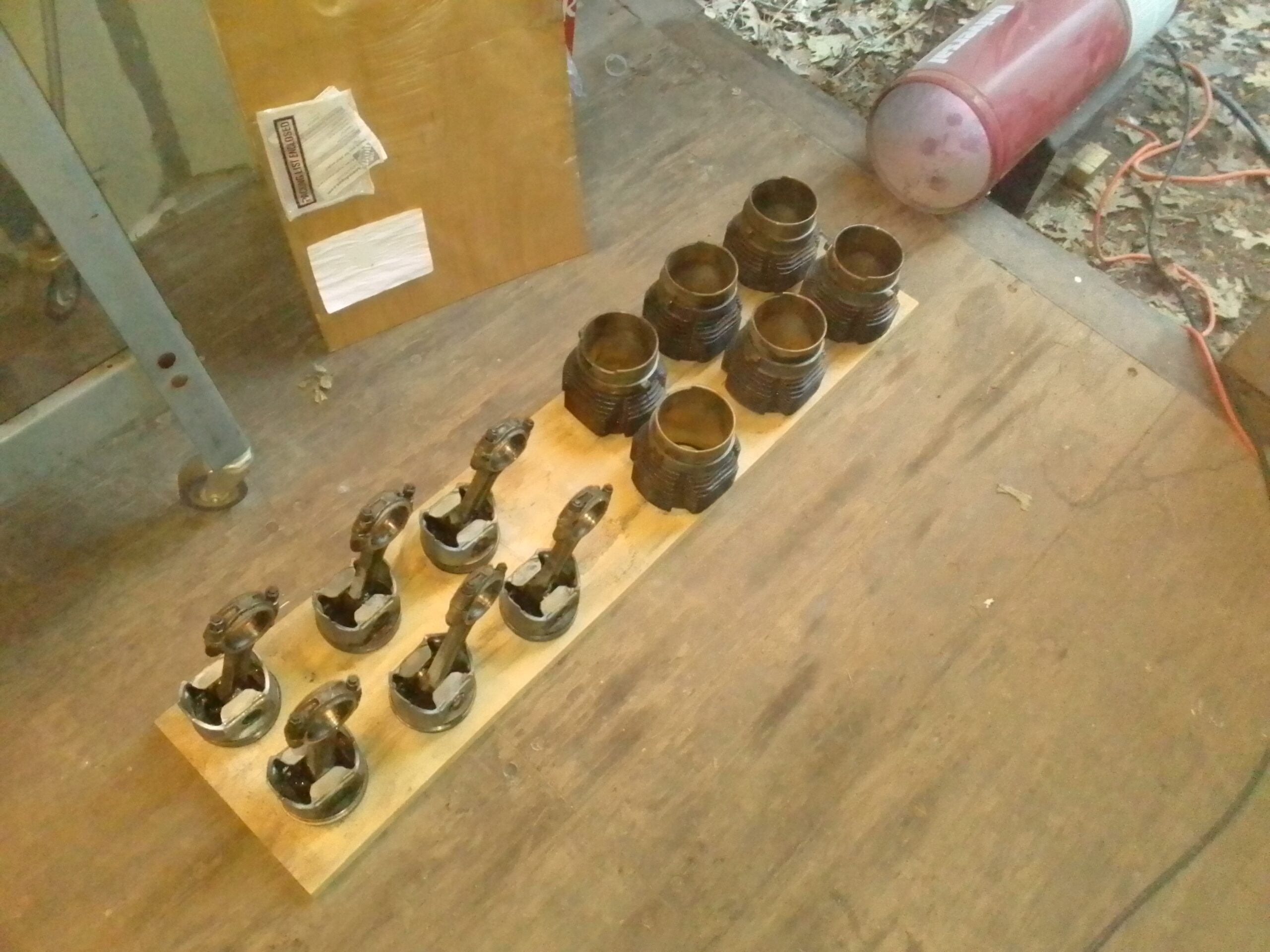
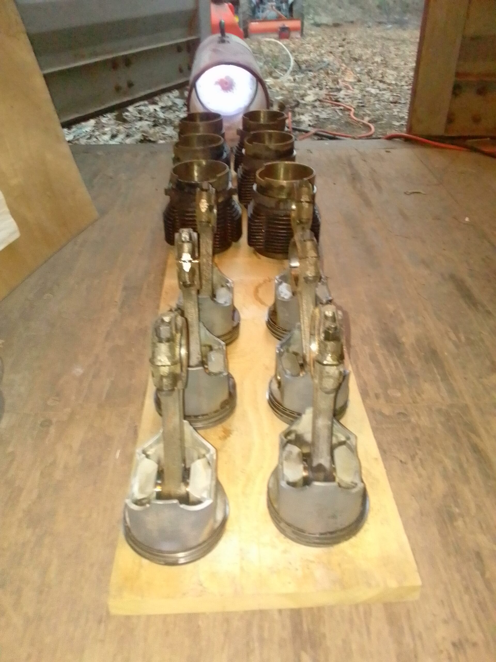
Using the same hot water and Purple Power process I soaked and pressure washed the cylinders, rods, and pistons in prep for core ship to Clark’s Corvair. Because these parts were made of steel and rust was an issue they required a bit more prep. After washing I immediately put them in front of the shop heater to dry:
Cooking of the water with shop heater150K BTU per Hour dried things quite well 🙂
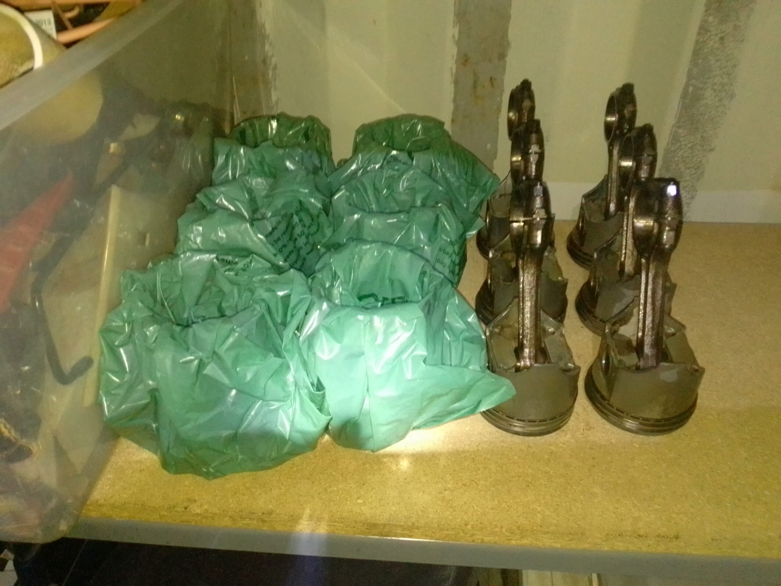
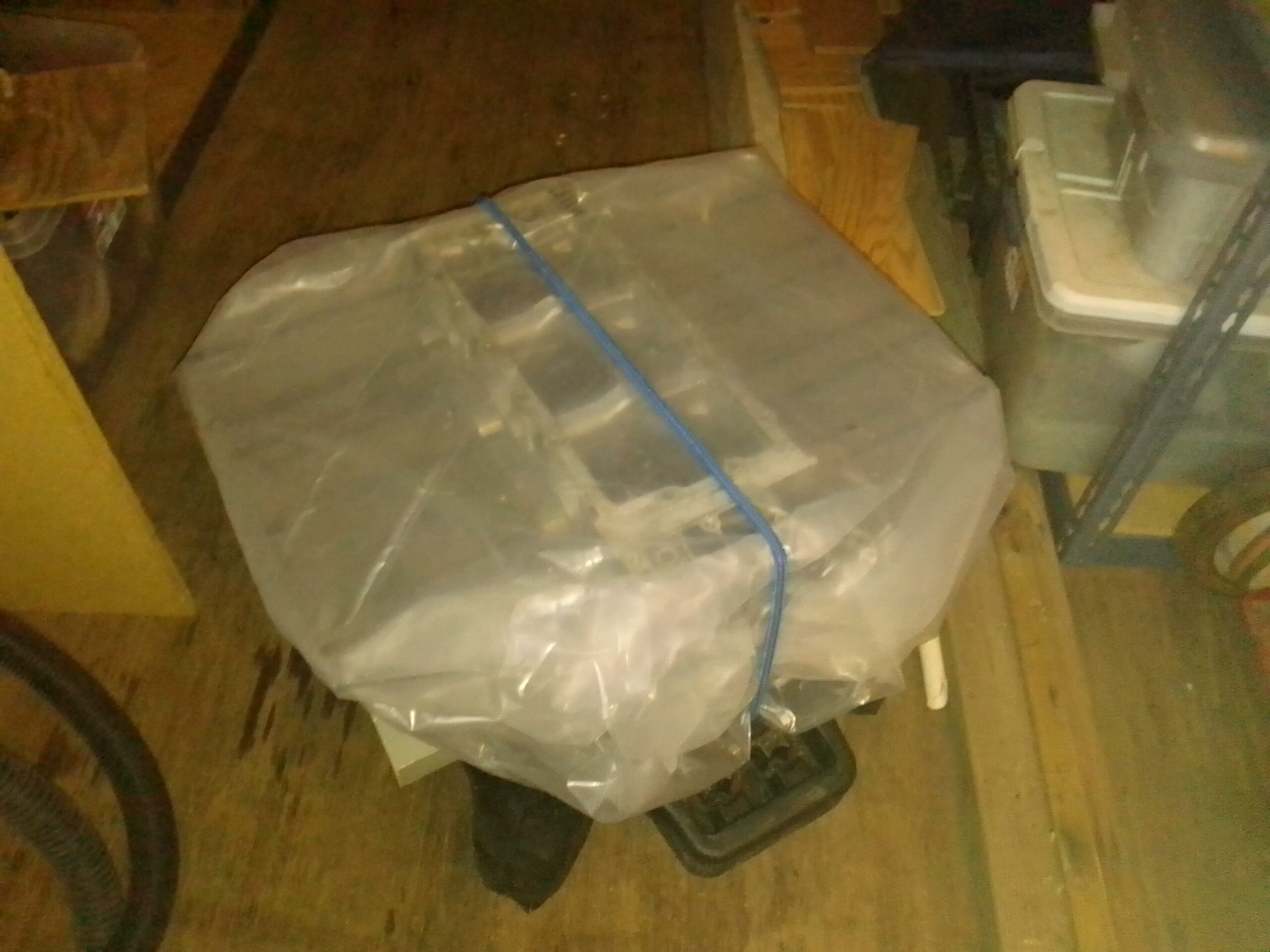
After drying I sprayed everything down with 2-26 lube and wrapped the cylinders with grocery bags. Cores all ready to ship to Clark’s:
Pistons, rods, and cylinders ready for core
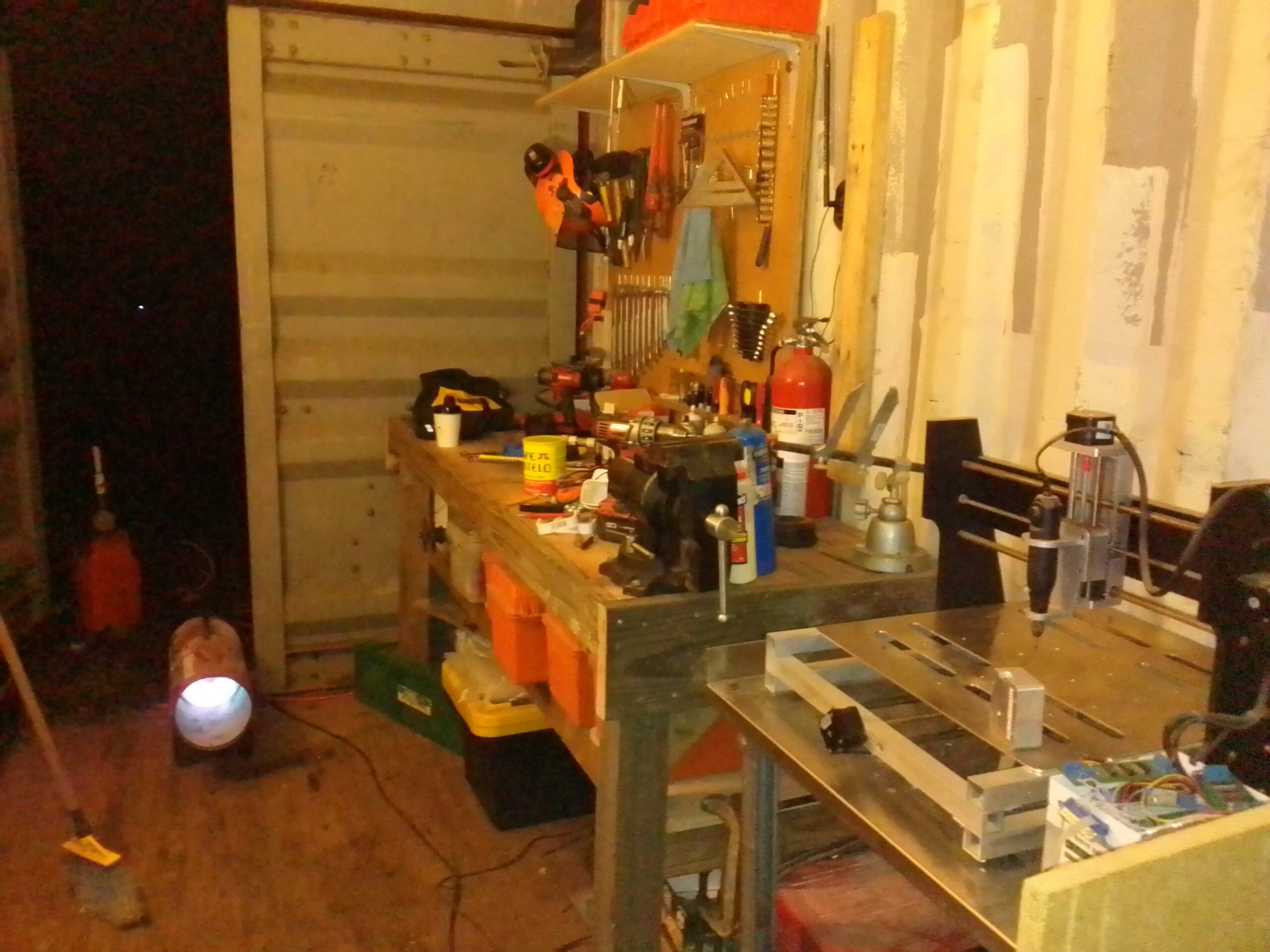
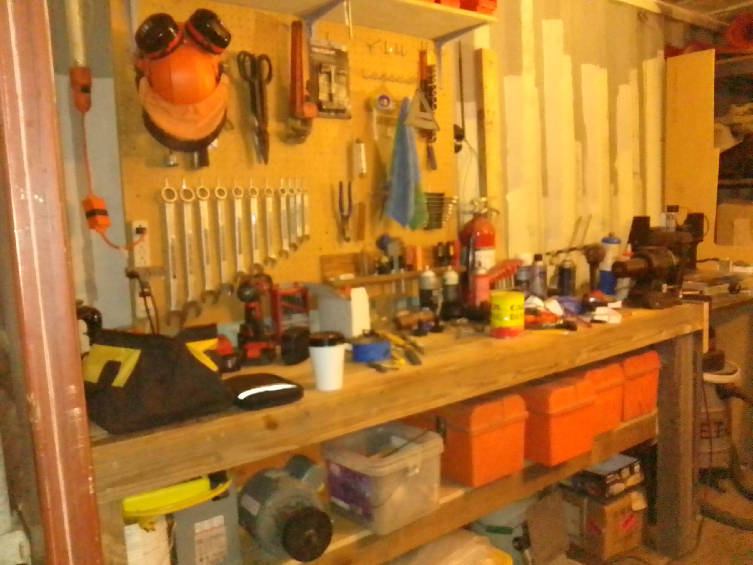
As I impatiently await the arrival of parts, the shop continues to improve:
WorkbenchPegboard and workbench in progress
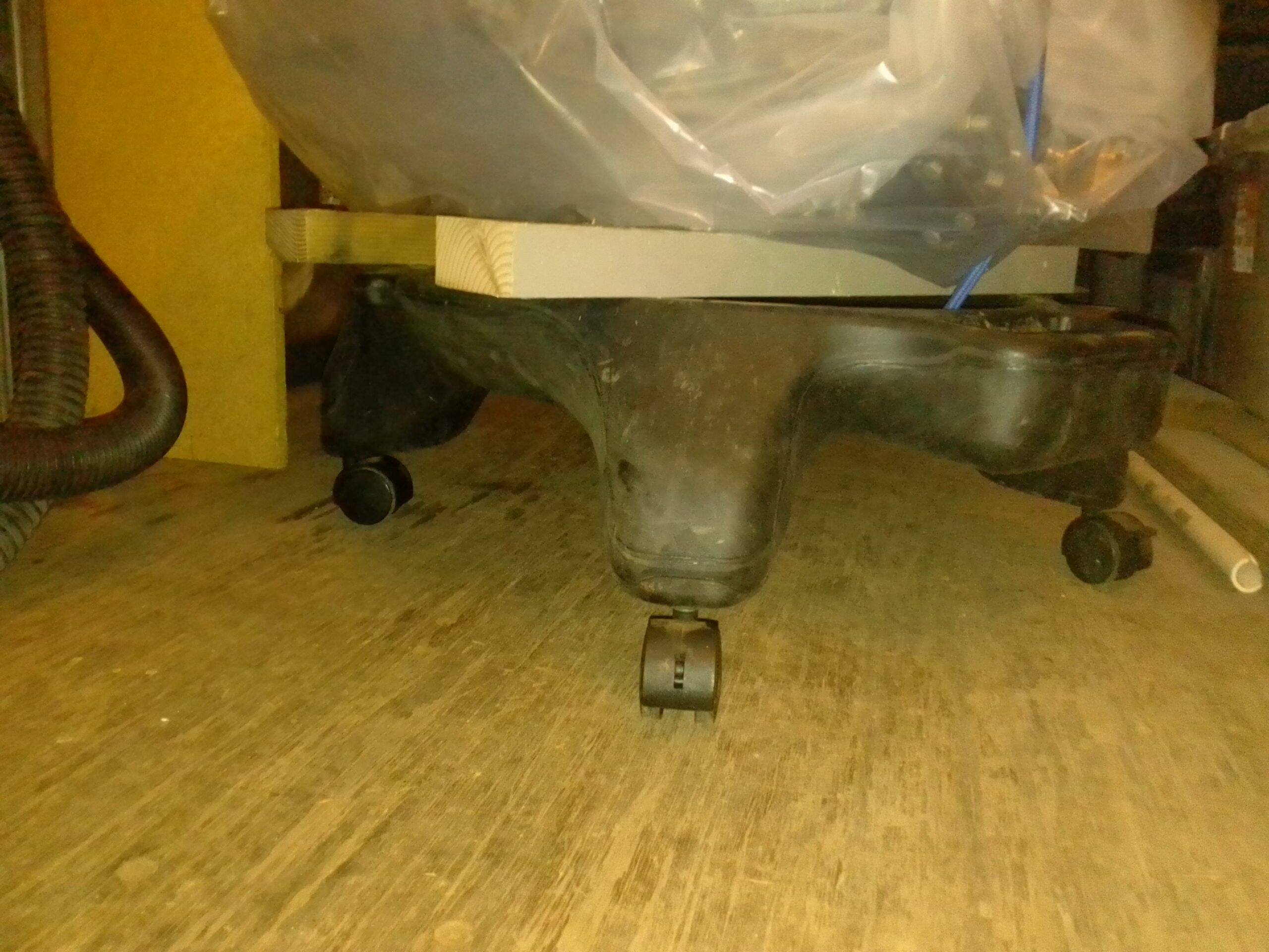
Finally I needed to make it easy to move my engine around. I used the base off of an old office chair to make an engine dolly. I just screwed some 2×4’s to the base. Works great:
Old office chair converted to engine dollyShort block prepped and wrapped for core
That’s all for today. Initial goodies from Aircraft Spruce are on the way so stay tuned!!!
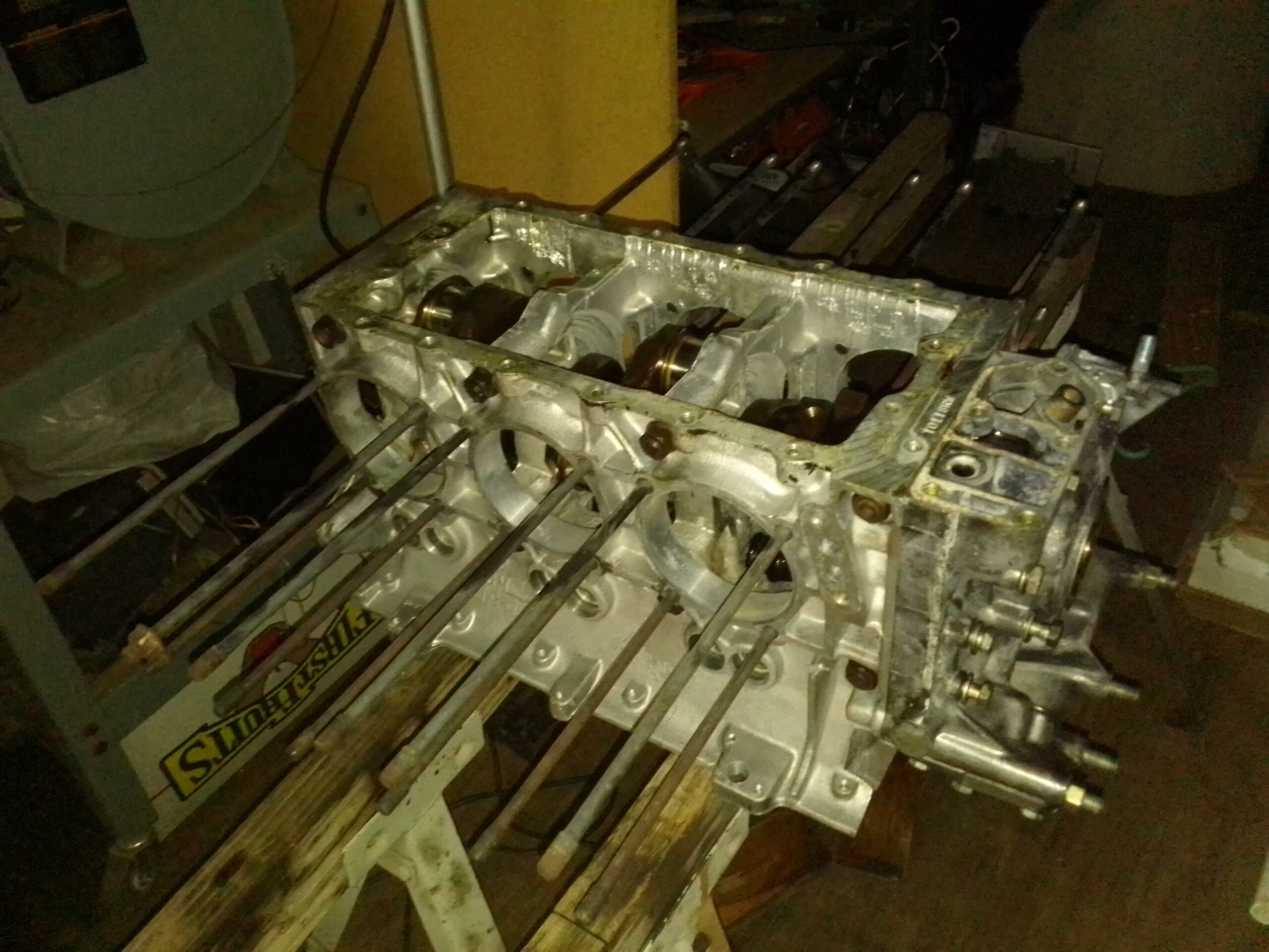
I have ordered the short block assembly, top cover, distributor, and the rear starter/alternator assembly. It is being built by Bill over at Azalea Aviation in Georgia. I have my “core block” all ready to go, so when my engine arrives I will use that crate to ship my core back. Here is the cleaned and gently assembled core ready for shipping:
Case prepped for rebuild core
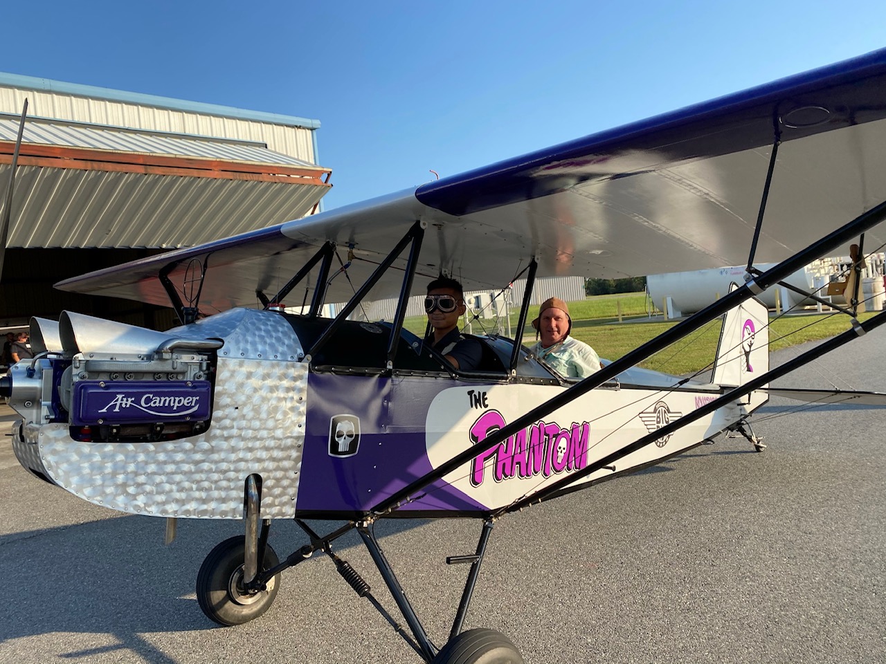
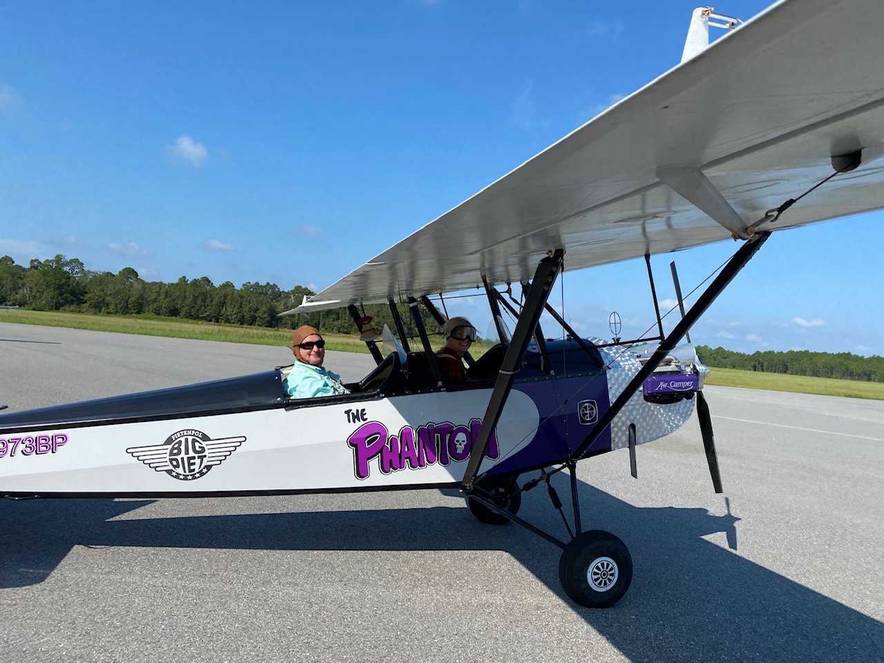
Tomorrow I will be ordering the tail section kits and Pietenpol plans from Aircraft Spruce. Hopefully it will look as cool as Bill’s Piet:
Tomorrow I will also be core prepping my rods and cylinders for Clark’s Corvair. They will provide hardware such balanced rods, cylinders, forged pistons, lifters and gaskets. Bill at Azalea will do the heads and covers for me. Stay Tuned!
Off-Grid Sustainable Living & Life Hacking – DIY or DIE!
 To construct a single elevator piece (two are required), twenty two spruce parts must be cut, milled, and glued together. That’s 44 custom wood parts for the elevators. And then sanding. Lots of sanding…. No wonder it takes some people ten plus years to finish one of these babies.
 It’s finally starting to look like an aircraft part! I used gravity to hold the joints together as T-88 likes minimal clamping pressure. I used tape for clamping pressure around the spars to hold them against the trailing edge.
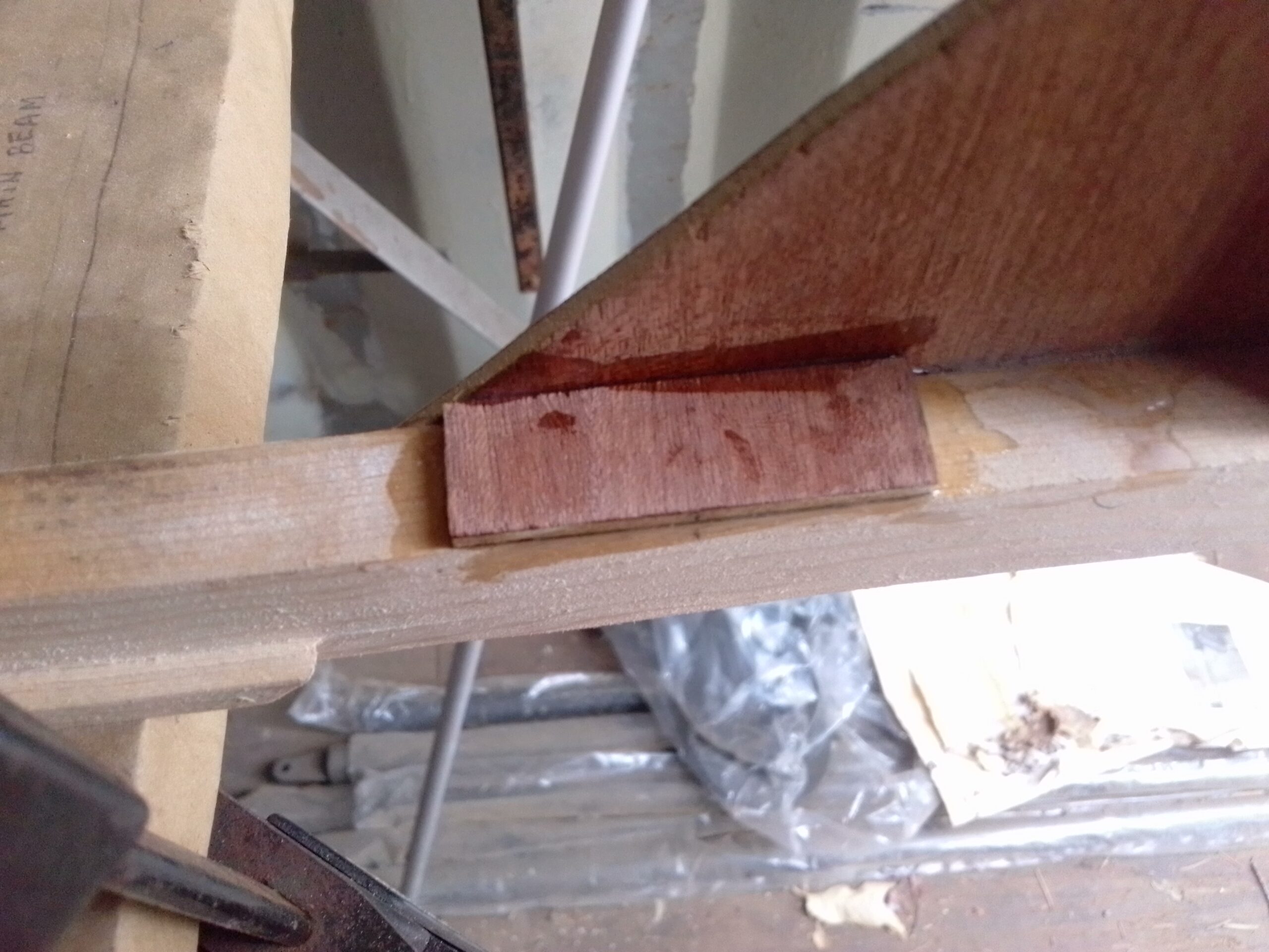
 You may have noticed that there are only gussets on one side of the leading edge. If you are building your own Piet, it is crucial that the hinges are installed before putting the gussets on the other side. Otherwise you will not be able to properly torque the hinge bolts.
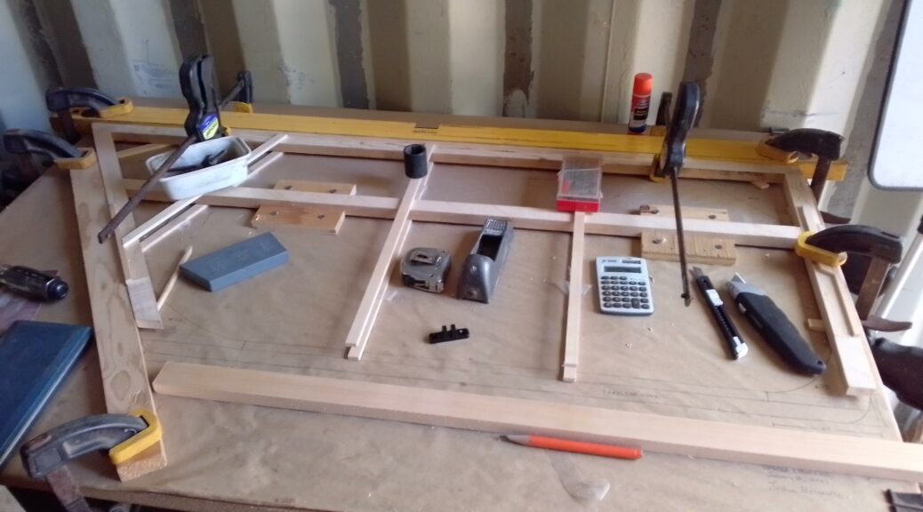


***obsolete, no replacement *** for Ryobi tools")